1 2 3 4
ON
5 6 7 8
1
2
4
8
16
32
5、门接
+
+
+
-
-
NC
NO
GND
COM
SEN
+
+
-
-
FR107
FR107
6. Connection Of Lock
-
LED
1
2
3
4
5
1
2
3
4
5
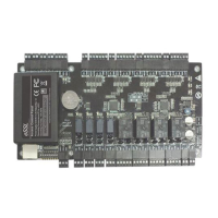
5. RS485 Address Setting, Restore Factory Setting, Terminal Resistance Setting
1 2 3 4
ON
5 6 7 8
Location of DIP switch
Set RS485 address through DIP switch:
1) Place 1-6 on DIP switch are for setting the number of control panels when communicating through RS485, it is adopted for binary coding,
and little endian, the address represented by place 1-6 are shown as figurue(5-1).
2) Before setting the address, please keep the system power off. Jump place 1-6 to desired status. The address number cannot be the
same as another one in the network. For example: to set the device number as 39 (39=1+2+4+32), the corresponding RS485 code is 111001,
then Jump place 1,2,3 an
d 6 at “ON” status.
3) Place 7 is for restoring factory default settings. Jump it for three times within 10 seconds and restart the system. All information in
control panel will be cleared and the system restores factory default settings.RAM
4) Place 8 is for setting terminal resistance when communicating through RS485. Jump it at “ON” status, then it is equivalent to having
a terminal resistance of 120 ohm between 485+ and 485-.
Figure( 5 -1)
Restore factory setting
RS485 terminal resistance
3) When the Electrical Lock is connected to the Access Control Sys
tem, you need to parallel one FR107
diode (equipped in the package) to
prevent the self-inductance EMF affecting the system, do not reverse the polarities.
1) Control panel provides lock control output interfaces. For NO lock ,it is open when power is on, and closed when power is off, so COM and
NO interfaces should be used; For NC lock, it is open when power is off, and closed when power is on, so COM and NC interfaces should be
used.
2) Control panel supports “dry mode” and “wet mode” by setting the jumper, it is “wet mode” when connecting “V+ V-” Input interfaces to
supply power for loc
ks, please shorten 2-3 and 4-5 . Equipment factory default setting is dry mode. For setting “dry mode” and
please refer to <<C3-100/200/400 access control panel installation instructions>>.“wet mode”,
NO Lock
LOCK
LOCK
“Wet mode” wiring diagram of lock connecting with external power supply.
Enlarged diagram
of lock ports
NC Lock
Lock power
input
Diode
Diode
Jumper
terminal
11
1
1
TX
RX
TX
RX
ACT
LINK
POWER
CARD
RUN
V+
GND
IN
BUTTON4
GND
IN
BUTT
O
N3
GND
IN
BUTTON2
GND
+12V
WD1
WD0
READER4
GLED
BEEP
GND
+12V
WD1
WD0
READER3
GLED
BEEP
GND
+12V
WD1
WD0
READER2
GLED
BEEP
POWER
PC
L
A
N
NC
NC
NC
NC
COM
COM
COM
COM
NO
NO
NO
NO
COM
COM
COM
COM
NO
NO
NO
NO
NC
NC
NC
NC
L
OCK1
LO
CK2
LOCK4
LOCK3
GND
GND
GND
GND
SEN
SEN
SEN
SEN
V-
AUX1 AUX2
AUX3
AUX4
EXT
BUTTON1
READER1
+12V
GND
WD1
WD0
GLED
BEEP
+12V
GND
485-
485+
GND
GND
GND
GND
IN
IN
IN
IN
IN
GND
GND
485-
485+
AUXOUT1 AUXOU
T2 AUX
O
UT3 AUXOUT4
LOCK
GND
+12V
1 2
3
4
O
N
5 6 7 8
SD Card
Adva nced Acce ss Cont rol
1
1
1
1
TX
RX
TX
RX
ACT
LINK
POWER
CARD
RUN
V+
GND
IN
BUTTON4
GND
IN
BUTTON3
GND
IN
BUTTON
2
GND
+12V
WD1
WD0
READER4
GLED
BEEP
GND
+12V
WD1
WD0
READER3
GLED
BEEP
GND
+12V
WD1
WD0
READER2
GLED
BEEP
POWER
PC
LA
N
NC
NC
NC
NC
COM
COM
COM
COM
NO
NO
NO
NO
COM
COM
COM
COM
NO
NO
NO
NO
NC
NC
NC
NC
LOCK1
LOCK2
LOCK4
LOCK3
GND
GND
GND
GND
SEN
SEN
SEN
SEN
V-
AUX1 AUX2
AUX3
AUX4
EXT
BUTTON1
READER1
+12V
GND
WD1
WD0
GLED
BEEP
+12V
GND
485-
485+
GND
GND
GND
GND
IN
IN
IN
IN
IN
GND
GND
485-
485+
AUXOUT1 AUXOUT2 AUXOUT3 AUXOUT4
LOCK
GND
+12V
1 2 3
4
ON
5 6 7 8
SD Card
Adv anc ed Acc ess Con trol
 Loading...