Page 3 of 10 D A T A S H E E T 85005-0131
Not to be used for installation purposes. Issue 7
Panel Operation Options
Language English or French
Marketplace U.S. or Canada
AC fail delay Off: Off-premise notification of an AC power failure
is immediate.
1 to 15 hours: Delays the off-premise notification of
an AC power failure by the time period selected.
Zone resound On: NACs resound each time a device in the zone
goes into alarm even if they were silenced
Off: Inhibits the NACs from turning on again (after
they were silenced) when a second device in the
zone goes into alarm.
Reset inhibit after
NACs turn on
Off: Panel reset is operational immediately.
1 minute: Panel reset is inhibited for one minute.
Auto signal
silence
Off: Allows immediate silencing of signals from an
off-normal condition using the Signal Silence button
5 to 30 minutes: Delays the silencing of signals
from an off-normal condition by disabling the Signal
Silence button for the time period selected.
Day start Start time for daytime sensitivity
Night start Start time for nighttime sensitivity
Date U.S.: MM/DD/YYYY, Canada: DD/MM/YYYY
Sounder Base Six configuration settings
Mapping Disabled: Device mapping is not available
Enabled: Device mapping is available
LCD banner Banner text for line one and line two. Each line is
capable of up to 20 characters.
Event notification Zone: When a device is a member of a zone, only
the zone information is sent to the LCD display,
LEDs, printer, and dialer.
Zone/device: Zone information is sent to the LCD
display and LEDs. Device information is sent to the
printer and dialer.
Device: Only device information is reported.
System LEDs
LED Description
Alarm Red LED. Flashes when there is an active alarm
event on any loop. On steady once acknowledged.
Trouble Yellow LED. Flashes when there’s a fault with a
monitored circuit or system component or when a
circuit is disabled. On steady once acknowledged.
Sup Yellow LED. Flashes when there is an active super-
visory event on any loop. On steady once acknowl-
edged.
Ac Power Green LED. On when the panel has AC power.
Disable Yellow LED. Double-flashes when there is a dis-
abled circuit, alarm relay, or remote annunciator.
Ground
Fault
Yellow LED. On steady during an active ground
fault.
Test Yellow LED. Flashes when performing an audible
walk test. Steady indicates a silent test.
Monitor Yellow LED. Flashes when there is an active monitor
event on any loop. On steady once acknowledged.
Service
Detector
Yellow LED. Indicates that detector needs servicing.
Signal
Silence
Yellow LED. On steady indicates that NAC circuits
are turned off but the panel is still in alarm.
Remote
Discon-
nect
Yellow LED. On steady indicates that the dialer is
disabled or that the alarm relay is enabled or dis-
abled when the dialer is set to modem only.
Drill Yellow LED. Indicates that the panel is in drill.
Reset Yellow LED. Indicates that the panel is resetting.
Panel
Silence
Yellow LED. Indicates that the panel has been
silenced during an active trouble, supervisory, or
alarm event and indicates that new event activa-
tions have been acknowledged.
User Keys Yellow LED. Indicates the programmed key function is active.
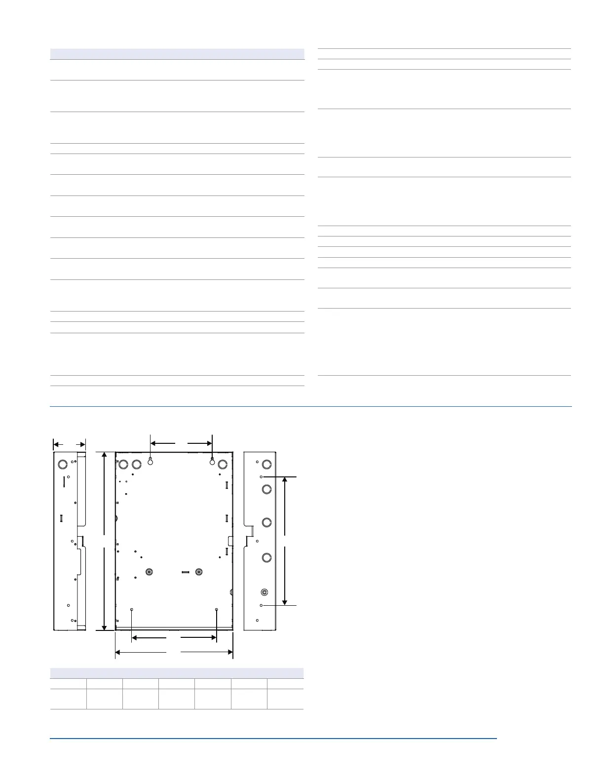
Dimensions
D1
D2
D3
D4
D5
D6
Surface mounting holes
Semi-flush mounting holes
Surface mounting holes
Panel dimensions, in (cm)
Model D1* D2 D3 D4 D5* D6
iO64
21.50
(54.6)
3.85
(9.8)
7.5
(19.0)
15.5
(39.4)
14.25
(36.2)
10.25
(26.0)
* Add 1-1/2 in. (3.81 cm) to D1 and D5 dimensions for trim kit.
Programming
iO-Series life safety systems are simple to set up, yet also offer ad-
vanced programming features that put these small building panels
into a class of their own. The auto programming feature quickly
gets the panel operational using factory default settings. Basic
zone and point settings can be programmed easily through the
front panel interface, so the system is up and running in no time.
For more advanced system configuration and correlation groups
programming, iO-Series systems interface to a PC running com-
patible iO-CU software. This option offers full system configuration
in the familiar Windows
®
operating environment. Connection is
typically made to a laptop through the panel’s optional RS-232
communications port, which can also be used to connect a sys-
tem printer.
Among the many advanced features of iO-Series control panels
is the optional network card. This module provides a standard
10/100 Base T Ethernet
®
network connection that permits access
to the control panel from any remote location with the correct
communications protocols. The connection can be used to
download to the panel from the iO-CU, or upload and view system
reports using the iO-CU.
Available system reports include:
• Correlation groups • Device details
• Device maintenance • History
• Internal status • System configuration
• System status • Walk test
• Dialer • CO runtime
 Loading...