Page 4 of 10 D A T A S H E E T 85005-0131
Not to be used for installation purposes. Issue 7
Wiring & Configuration
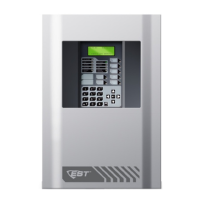
Notification appliance circuits (TB2)
The iO64 comes equipped with two notification appliance circuits.
Each circuit can be individually configured for continuous, tempo-
ral, synchronized, latching, and coded output.
Circuit Specifications
Circuit Type 2 Class B, Class A optional when Class A card is
installed.
Each circuit is 2.5 amps.
Voltage 24 VFWR
Current 3.75A total (115/230 60hz)
3.0A total (230v 50hz)
2.5 A max per circuit
Impedance 26 Ω total, 0.35 µF max
EOLR 15 K Ω, ½ W
+
NAC1
-
NAC2+
NAC2
-
NAC1+
EOLR
TB2
+
+ +
Class B wiring
Class B wiring
TB2
TB6
EOLR
NAC3
-
NAC4+
NAC4
-
NAC3+
EOLR
NAC1
-
NAC2+
NAC2
-
NAC1+
+ +
+ +
+ +
+ +
Class A wiring
TB2
TB6
NAC1
-
NAC2+
NAC2
-
NAC1+
+ +
+ +
+
+
- -
- -
Signature Device loop
The system provides one device loop circuit that can be used
with any mix of Signature Series detectors and modules. The loop
circuit is supervised for opens, shorts, and grounds.
The Signature Loop Controller uses broadcast polling and ad-
vanced communications formats to regularly check the entire
device circuit for anomalies. If a change of state is detected at the
circuit level, the Loop Controller then uses a direct address search
to find the reporting device. This two-staged technique ensures
that only new information is transmitted, thus allowing for a re-
duced baud rate while still achieving nearly instant device reporting.
Circuit Specifications
Device loops 1 loop Class B, Class A optional when Class A card
is installed. Supporting up to 64 device addresses.
Communication
line voltage
Maximum 20 V peak-to-peak
Circuit current 0.5 A max
Circuit
impedance
66Ω total, 0.7 µF, max
Isolators 64 maximum
Loop 1 SEC
Loop card
+
Loop 1 PRI
+
+
+
Loop
device
Loop
device
Data Line
Class B wiring
Class A wiring
Loop 1 SEC
+
Loop 1 PRI
+
+
+
Loop
device
Loop
device
Loop card
Data Line
-
-
- -
Loop 1 SEC
Loop card
+
Loop 1 PRI
+
+
+
Loop
device
Loop
device
Data Line
Class B wiring
Class A wiring
Loop 1 SEC
+
Loop 1 PRI
+
+
+
Loop
device
Loop
device
Loop card
Data Line
-
-
- -
-
-
- -
Class B Wiring Class A Wiring
Marking indicates output signal polarity when the circuit is active.
Polarity reverses when the circuit is not active. Wire notification
appliances accordingly. Notification appliance polarity shown in
active state.
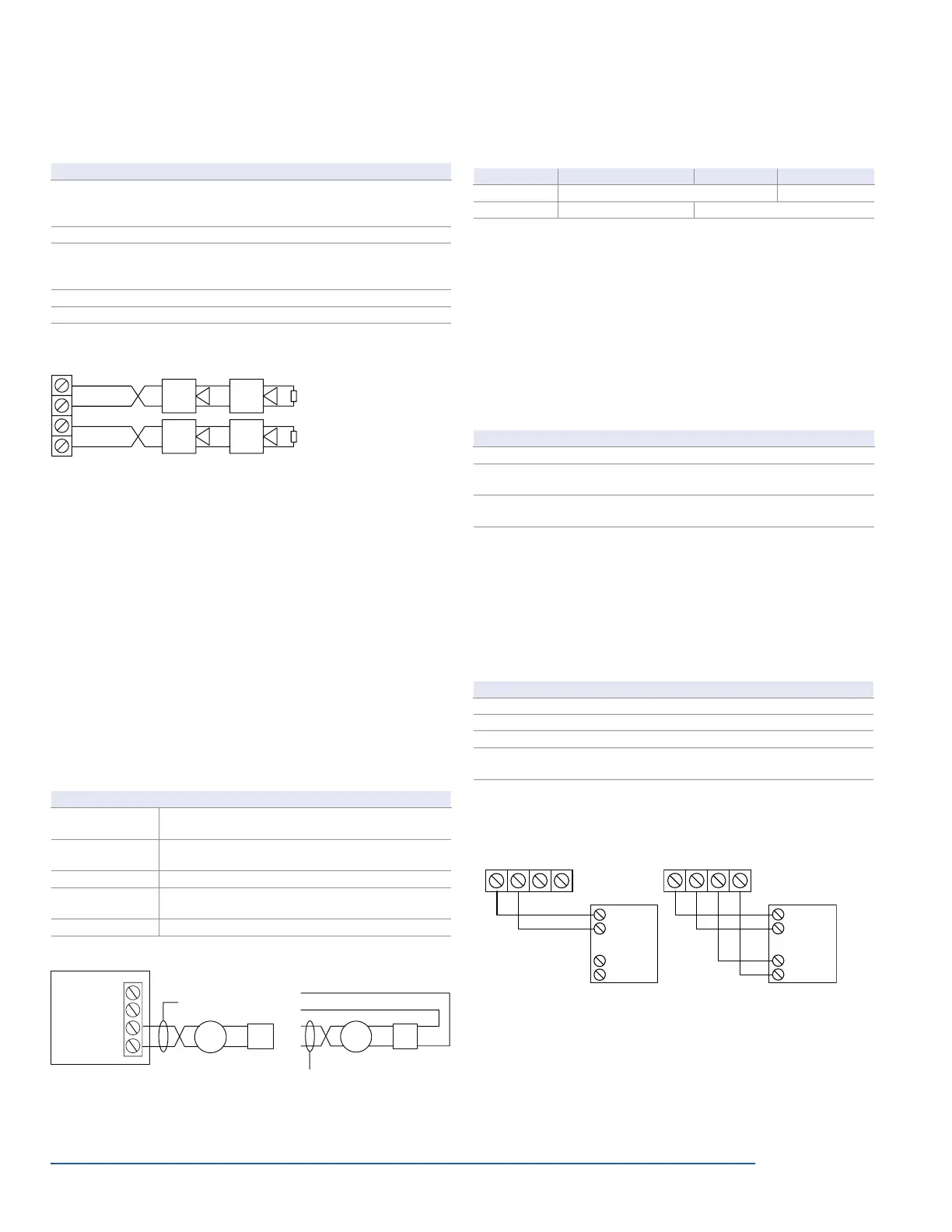
Annunciator loop (TB4)
The control panel provides a connection for up to eight serially
driven and supervised remote annunciators.
Circuit specifications
Device loops Class B (Style Y) or Class A (Style Z)
Circuit voltage 2.55 V
Circuit current 30 mA max
Circuit
impedance
Up to 8 annunciators or 4000 feet
+
–
TB4
+
–
Channel 1 Channel 2
CH1 (+) IN
CH1 ( ) IN
–
CH2 (+) IN
CH2 ( ) IN
–
Annunciator
hannel 2
CH1 (+) IN
CH1 ( ) IN
–
CH2 (+) IN
CH2 ( ) IN
–
Annunciator
Terminal wiring location
+
–
TB4
+
–
Channel 1 Channel 2
CH1 (+) IN
CH1 ( ) IN
–
CH2 (+) IN
CH2 ( ) IN
–
Annunciator
+
–
TB4
+
–
hannel 1
hannel 2
CH1 (+) IN
CH1 ( ) IN
–
CH2 (+) IN
CH2 ( ) IN
–
Annunciator
Class B Class A
Alarm, trouble, and supervisory relay (TB3)
The trouble relay is normally-open, held closed, and opens on any
trouble event or when the panel is de-energized. The supervisory
relay is normally-open, and closes on any supervisory event. The
alarm relay changes over on any alarm event.
Relay specifications
Alarm Trouble Supervisory
Type Form C Form A
Voltage 24 VDC at 1 A resistive 24 VDC at 1 A resistive
Relay circuits can only be connected to power-limited sources.
Auxiliary & Smoke power outputs (TB3)
The control panel provides two auxiliary power outputs which can
be used for powering ancillary equipment such as remote an-
nunciators and two wire smoke detectors. Aux 2 can be software
selected to operate continuous. The circuit is supervised for shorts
and grounds.
Note: For a complete list of devices that can be connected to this
circuit, refer to the iO Series compatibility list (p/n 3101064).
Circuit specifications
Circuit voltage range 21.9 to 28.3 V
Resettable circuit
(Aux power 2)
24 VDC nominal at 500 mA
Continuous circuit
(Aux power 1)
24 VDC nominal at 500 mA. Use this circuit for
powering two-wire smoke detectors.
Note: Any current above 0.5 amp connected to both Aux 1 and 2 will reduce the total
available NAC power by that amount.
 Loading...