Page 4/16 BEA--206006-EN-04
2.3 Mode of operation
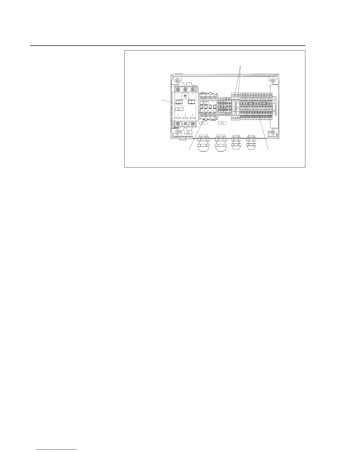
Motor protec-
tion switch
Contactor
Fuses
Switch panel SE 12521
Connection terminals
The HP 03.. controller is available in three dierent electrical versi-
ons.
- Switch panel SE 12521 with motor protection switch, three-phase
a.c. motor contactor and connection terminals for the valve wiring.
- Terminal box SZ 0921 with connecting terminals only for the three-
phase a.c. motor and valve wiring.
- No electrical wiring.
To generate the air required for sensing, ambient air is drawn into the
side channel compressor and fed to connection S 1 of the pneumatic
sensor. The level of the probing air pressure and thus the control
sensitivity for adjustment to dierent situations is set via a restrictor.
Some of the compressed air is sent to diaphragm D 1 (see pneu-
matic system plan on opposite page, at top). A pressure spring works
in the opposite direction to the dia grapm. If the sensor is covered ap-
propriately, the diaphragm is maintained in the center and the system
in a zero position.
If the web moves away from the zero position, it changes the air cur-
rent which, in turn, inuences the diaphragm. The change to the dia-
phragm directly aects the servo-valve controlling the uid ow. The
uid ow changes the location of the positioning cylinder until the
web returns to its zero position.