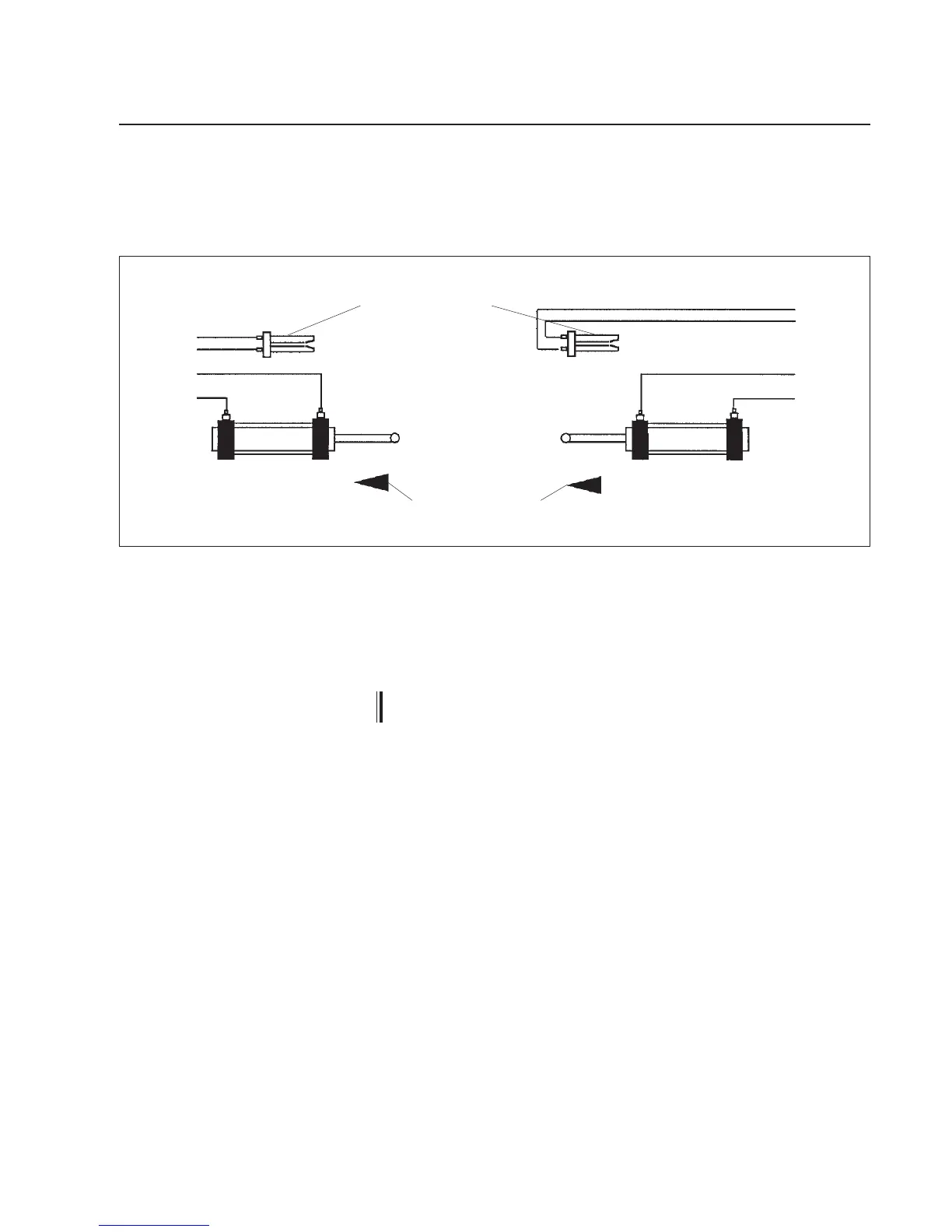
The positioning cylinder should be connected as follows.
When the FL 2.. pneumatic sensor is uncovered, the uid ow is from
to A to B.
The positioning cylinder must be connected so that it moves towards
the pneumatic sensor (see g. below)
Positioning cylinder stroke
Positioning cylinder
Positioning cylinder
A
B
Connec-
tion to
controller
Uncovered pneumatic sensor FL 2..
Positioning cylinder connection
The electrical connections should be carried out according to the at-
tached connection diagram.
Controller HP 03.. should be connected to the mains via an
electrical fuse.
5. Installation
4.3 Positioning cylinder
A
B
Connec-
tion to
controller
 Loading...