Page 8/16 BEA--206006-EN-04
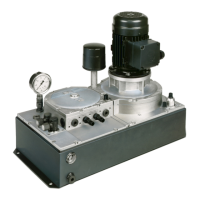
The switch panel or terminal box can be mounted in three positions
(see g. below).
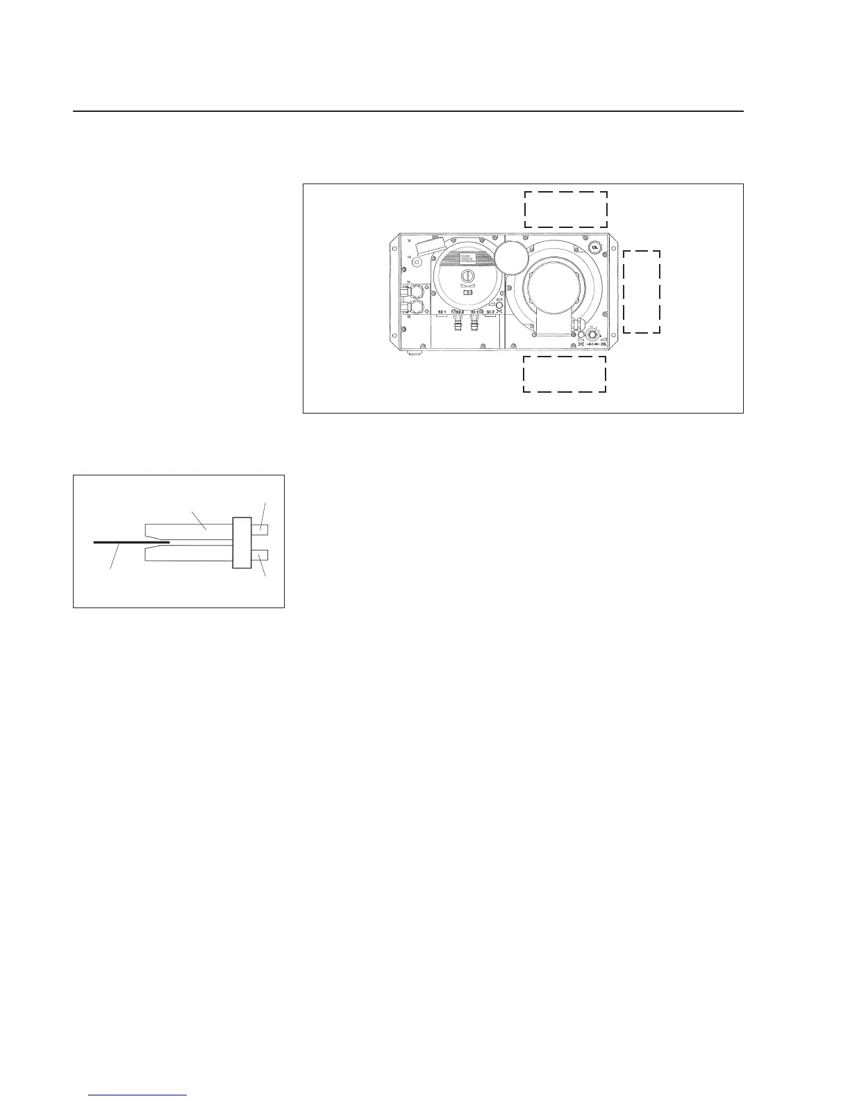
When the web passes through the air sensor on the horizontal, sen-
sor connection S 1 should be located underneath the web (see g.
on left). This protects the air sensor from soiling.
The pneumatic sensor should be connected as follows.
Connect S 1.1 on controller to sensor via S 1.
Connect S 2.1 on controller to sensor via S 2.
The air lines to the sensor must be of the same length and not ex-
ceed 3 m. The line to the pneumatic return-to-center switch must not
exceed 6 m. Narrowing of cross- sections and narrow hose elbows
are not permissible due to the danger of rupture. For temperatures
over 70 °C, silicon hoses should be used for the air lines and copper
pipes for the hydraulic lines.
The plastic tubes supplied (6 mm inner diameter, 10 mm outer dia-
meter) should be used for the hydraulic lines. When using steel pipes
(10 mm x 1 mm) these must be cut to size using a pipe cutter. The
pipes must be cleaned prior to installation. The hydraulic lines must
securely xed.
Mounting options
Standard
A
B
C
Air sensor
Web
S 1
S 2
Pneumatic sensor FL 2..
4.2 Switch panel
4.3 Pneumatic sensor