9
6 BLOCK REMOVAL
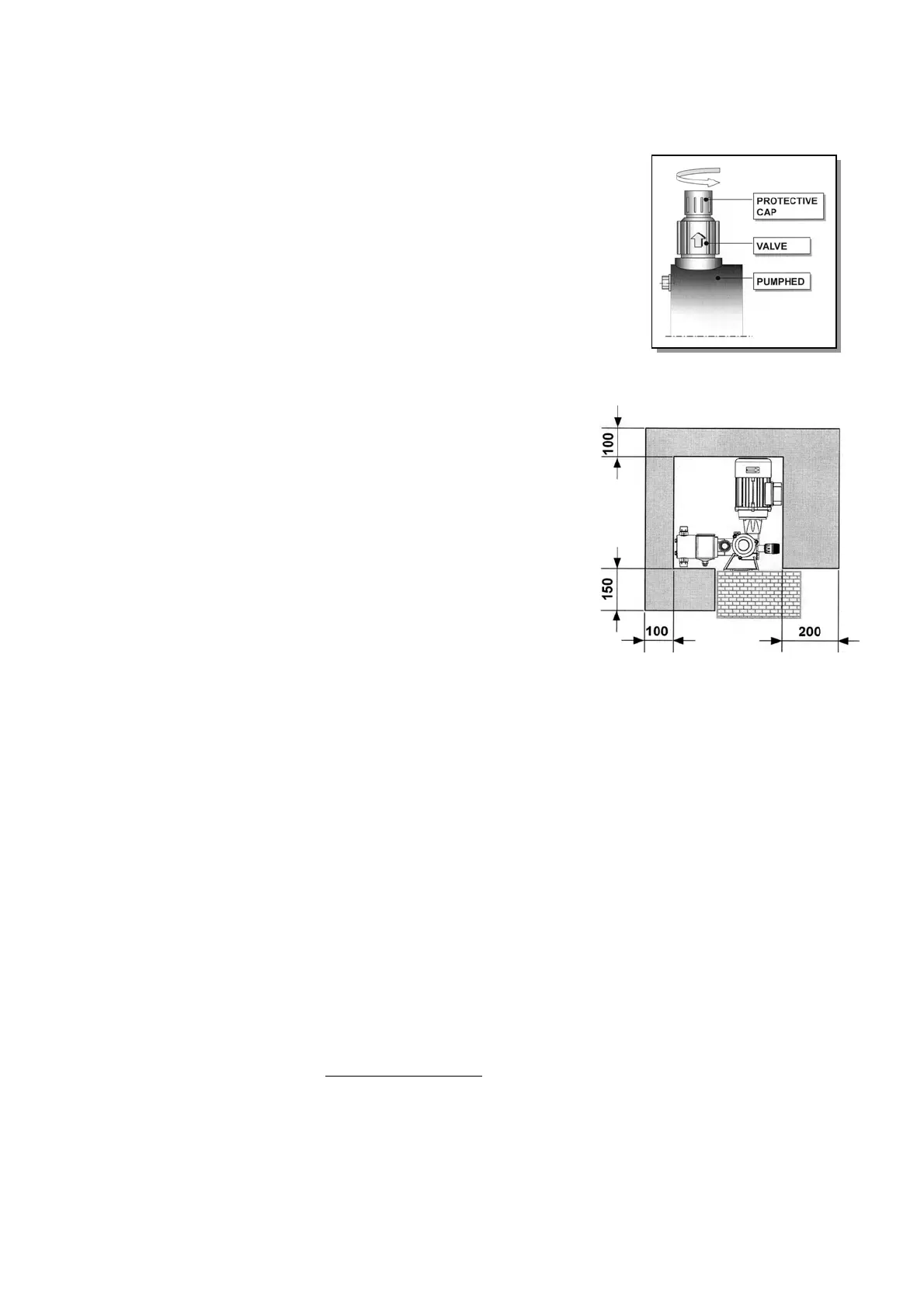
Before installing the pump, make sure to remove all protective caps
located on the suction inlets and the valve delivery system.
7 PUMP INSTALLATION
9 Allow enough room (operation areas) to check and
disassemble the pump, particularly on the hydraulic side
(pumping head) and next to the adjustment knob.
9 We recommend you install outlets along the delivery pipe
and near the pumping head to empty the liquid from the
plant.
9 If the pump is installed outdoor, a suitable shed is
required, particularly if it is equipped with a plastic head,
servo controls or other delicate instruments.
9 Beyond standard caution, we recommend the installer
and/or construction engineer to install the pump in a well-
ventilated environment or on board of machinery to allow
any liquid that may come out to drain off, thus preserving
facilities and ensuring good maintenance.
8 PUMP POSITIONING
9 The pump must be installed on a strong base (made of metal, cement, etc.) which ensures
stability and levelling of mount and has a suitable grade, preventing any strain on the axis.
9 The pump should be placed downstream and the suction pipe should be as short as possible
and provided with wide-angle bends for easy pumping of fluid.
¾ Manually check the motor fan for loose rotation of the pump.
If the fan is stuck, check pump positioning and pipe alignment.
9 CONNECTING THE PUMP TO THE SYSTEM PIPES
9.1 CONNECTION TO THE SUCTION PIPE
Following are some recommendations installers should follow for proper installation.
9 The suction pipe should be as short as possible. On each angle place a wide-angle bend.
9 Before connecting the pipes to the pump connections, wash the pipes of any stray fragments,
welding drops, pieces of gaskets, etc.
9 Avoid creating a reverse grade to let air bubbles out and make sure the suction system is air-
tight for easy activation of the pump.
9 The diameter of suction pipes must be larger than the pump valves.
9 Speed of fluid in pipe cannot exceed 0.7 m/s for liquids with viscosity up to 100 mPa - (cPs).


 To Next Page
 Loading...