Generator G11 Service Manual
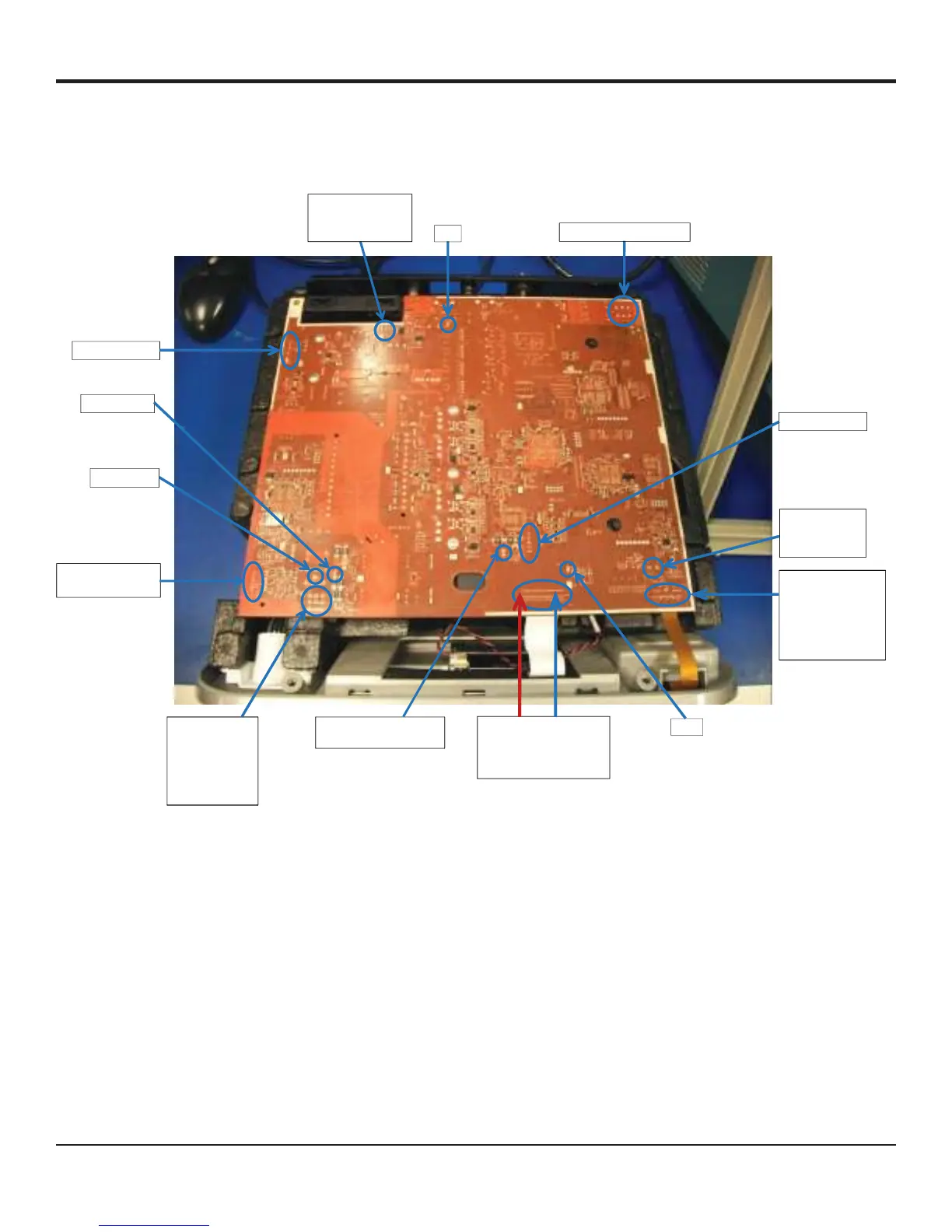
Additional Hardware Troubleshooting Information
Note:
J29 – LCD connector, FB22
is fourth via from the right
(blue arrow points to it),
CC signal is red arrow
J25 – Backlight connector
(arrow pointing to pin 1)
J28 – Power pins
from receptacle
Numbering:
1,2,3
4,5,6
7,8,9
J30 Bezel Connector
Pins in order from
edge of PCB – Pins
1, 2, 4, 6, 7, 8, 9, 10,
11, 12, 13, 14, 15, 16,
18, 19
J23 – speaker
connector (pin o
is square one)
J27 heat sink fan
TP2, TP3, TP4, TP5
Footswitch signals
(Top left one is TP2)
J24 EEPROM signals
square pin is
TP62 RF out
TP27 HS out
J8 Enclosure Fan
J4 Power Supply input out
TP1
TP60
Figure 47 - Access Points Used For GEN11 Troubleshooting While Powered