LLeeaadd NNuulllliinngg
Test Leads are nulled to ensure
accurate resistance values of
circuit under test. To achieve
this you must null the
resistance of the leads in use.
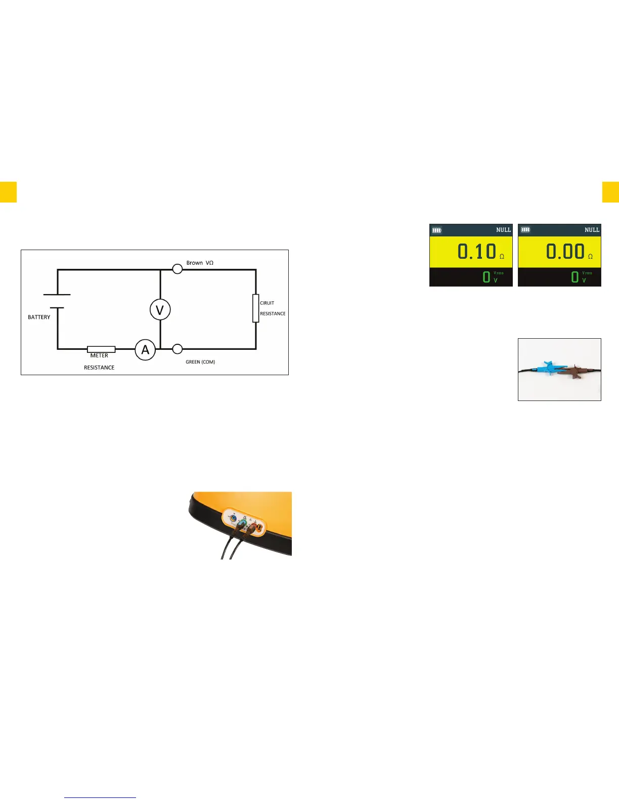
Using the croc clips connect
the open ends of the test leads
together firmly ensuring a good connection, then press
continuity null button, the instrument will display the resistance
value of the test leads, then press the test button, the display
will then show 0.00Ω and your test leads are successfully
nulled. The word Null will appear on the display.
IMPORTANT – When connecting the croc clips they must
be connected as diagram shown this ensures that the best
point of contact is made to give the most accurate
resistance value of the leads that will be used for testing.
If inserting new or different length leads you must repeat
process above.
N.B. Nulled results will be stored until user reset. To reset
simply leave the Ethos 8400 in continuity mode and open circuit i.e. do not have leads
connected. Then press NULL this will then remove the null function.
The Ethos 8400 is now correctly set up to perform continuity testing on a circuit.
You can also set up your Ethos 8400 to be used in hands free mode on continuity by simply
pressing the test lock button and then pressing test.T-Lock will flash at the top of the screen to
indicate you are on hands free mode.To deactivate simply press test lock button again.
IInnssuullaattiioonn
WARNING
Do not touch the ends of the test leads while on the Insulation test functions as they are
energised.
Results of measurements can be adversely affected by impedances of additional
operating circuits connected in parallel or by transient currents.
11
EETTHHOOSS 88440000
INSTRUCTION MANUAL
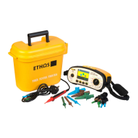
During continuity measurement current flows from battery positive through the Brown (VΩ)
lead, external circuit resistance, Green (COM) lead, meter resistance and finally back to the
battery negative.
The current and voltage are measured as shown on page 9 and the external resistance
calculated. When the leads have previously been nulled, their resistance is subtracted before
displaying the reading.
The purpose of Continuity Testing is to establish the resistance of the circuit under test.
TTeesstt PPrroocceedduurree
Insert the brown test lead into the brown input terminal & the blue test lead into the green
terminal.
The brown test lead can be substituted by using the red
remote test probe supplied.This allows remote
activation of the Ethos 8400 from the safety of the test
probe ensuring that you are always looking at the point
of contact and not the Ethos 8400.
Select continuity on the rotary switch.
10
EETTHHOOSS 88440000
INSTRUCTION MANUAL
CCoonnttiinnuuiittyy
PPrriinncciippaall ooff MMeeaassuurreemmeenntt
 Loading...