4930638-02 - Page 3
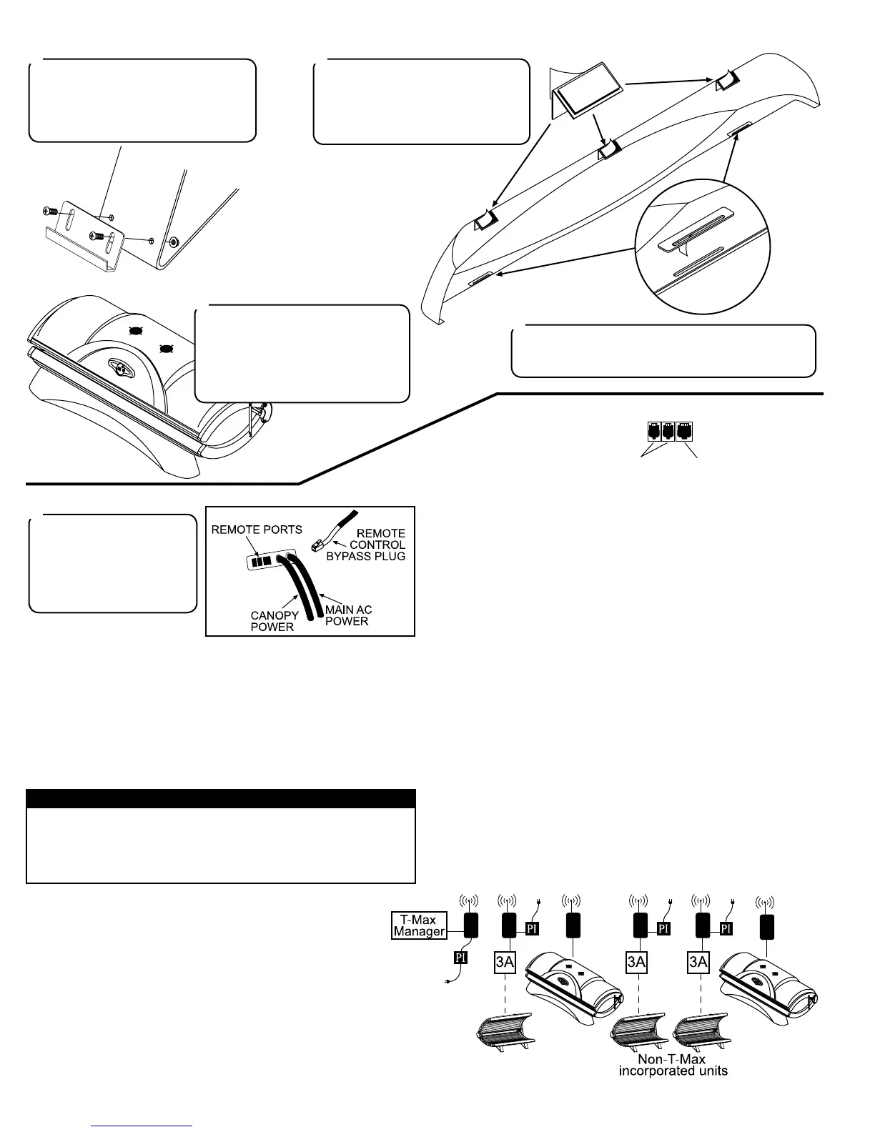
On the front of each leg are two holes
for skirt mounting brackets. Locate the
two brackets and attach them as shown
with two #10-32 x 1/2” screws and two
#10-32 locking nuts each.
12
Peel the backing from the double-
sided tape on each skirt top bracket
and attach them to the skirt as shown.
Make sure the corner lines up with
the top edge of the skirt as shown.
13
Slip the slots in the bottom of the skirt
onto the skirt mounting brackets.
Peel the backing from the Velcro®
pad on each top bracket and press
the top brackets to the bench cover.
Press rmly so the pads stick.
15
Peel the backing from the double-sided tape on each
skirt reinforcing plate and press them onto the skirt so
the slot in the plate lines up with the slot in the skirt.
14
The unit is shipped with a
Remote Control Bypass Plug
installed. Your sunbed will
not operate without either
the bypass plug or a remote
system connected.
16
Remote Connections
Your sunbed incorporates advanced circuitry allowing it to connect and
communicate with most remote control systems. If a remote system is
to be used, rst determine whether the remote system is a T-Max® Sys-
tem or a standard remote system operating with a control relay. Follow
the appropriate instructions for your system type.
T-Max® Products
The T-Max® remote systems offer the ultimate in sunbed control,
while allowing the tanner easy straightforward operation. Your
sunbed is congured to directly connect to this system, including
the new wireless remote system. The circuitry inside your sunbed
eliminates the need for the T-Max® 1A or 3A when connecting
to the T-Max® Manager series. Your sunbed supports the auto
addressing feature of the latest T-Max® Manager models and the
following parameters: 5, 6, 7, 8, 9, 10, 15 and 23. See your T-
Max® manual for descriptions of these parameters and how they
function.
T-Max® Wireless Remote System
The T-Max® G2 eliminates wires in your salon, allowing easy setup
without hiring an electrician to run wires. It also protects your invest-
ment from damage by isolating each unit from one another. Your sun-
bed arrives “wireless ready”, which means it connects directly to the
T-Max® wireless system. Older tanning beds, and T-Max® managers,
also utilize this system but require a T-Max “Power Injector” (PI) to pro-
vide the needed power to the wireless unit.
Remote System Hook-up Scenarios
Follow the diagrams below and on the next page to see the many differ-
ent scenarios for hooking up your salon. If you need further assistance,
call T-Max® directly at (417) 297-0361.
CAUTION
The remote connection is not designed to supply or accept high volt-
age, nor can it provide power to an external timer. The sunbed’s re-
mote interface circuitry operates on 5 volts, attempting to connect it
to any higher voltages will damage the sunbed as well as void your
warranty.
REMOTE PORTS
WIRED
REMOTE
PORTS (RJ-22)
WIRELESS
REMOTE
PORT (RJ-11)
Scenario 1 - T-Max® Manager Series with Complete Wireless
Connect one G2 (with Power Injector) to the Manager and one G2 to
each of the tanning beds. Install as many beds as you like with this
conguration. Units that do not communicate with T-Max will need an
G2 with Power Injector and an additional 3A to operate. If you have
an older T-Max® Manager that doesn’t support auto addressing, set the
address of each sunbed manually as described in Setting the address
manually. You can place your sunbed at any location in the series.
 Loading...