BE SURE THE UNIT DISCONNECT IS IN THE “OFF” POSITION
AND THAT ALL ELECTRICAL POWER TO THE UNIT IS
TURNED OFF BEFORE CLEANING THE SYSTEM.
Remove any loose grass, leaves, papers, etc., from the area
around the condenser coil. These could reduce the air supply
through the coil and reduce the amount of cooling capacity.
3. Since the air conditioner is located outdoors, it is exposed to all
weather elements. Treat it with a good automobile paste wax
twice a year (in the spring and fall).
Check with your contractor if you have any questions regarding
the maintenance or operation of your unit.
INSTALLATION
A
. CODES
The installer SHALL comply with all local, state, and federal codes
and/or regulations pertaining to this type of equipment and its
installation. Such codes and/or regulations should take
precedence over any recommendations contained herein.
Installations SHALL be made in accordance with the National
Electrical Code, local codes, and recommendations made by the
National Board of Fire Underwriters.
B. UNIT SITE SELECTION
1. To eliminate noise from being transmitted into noise
sensitive areas, the unit should NOT be installed on walls
adjoining bedrooms, sleeping quarters, or adjacent to
windows.
5. R
eturn and supply grilles must be used when the return
and supply are not ducted. When a supply grille is used
in the installation, the louver spacing must be no greater
than 5/8 inch.
6. If the factory-installed filter is used on your installation,
access to the filter is made through the center panel on the
front of the unit.
IF A REMOTE FILTER IS USED, SUCH AS A FILTER GRILLE,
THE FACTORY-INSTALLED FILTER MUST BE REMOVED AND
DISCARDED.
D. DUCTWORK
1. Properly-sized duct systems are critical for satisfactory
operation of any air conditioning system. All ductwork
MUST be correctly sized for the design air flow requirement
of the equipment.
2. The recommended operation duct static is to deduct 0.07"
W.C. for any size of heater 5 kW to 20 kW on factory or
field-installed heaters.
3. Ductwork routed through wall cavities, as well as any duct
not in conditioned space, MUST be insulated. Supply
ducting routed through exterior walls MUST be insulated
with 1" insulation to the back of the unit.
4. Supply and return air ducts should be flush with the exterior
wall and sized to fit over the unit duct collars in order to
compress the collar air gasket.
5. If supply duct is flashed to the exterior of a building
c
onstructed with combustible material, the flashing MUST
be insulated in order to maintain the required clearances
to combustible materials. Required clearance is 1/4" for
the first three (3) feet of supply duct.
E. FILTERS
system or area to be conditioned, will prevent lengthy duct
1. One-inch disposable filters are supplied standard in each
runs and unnecessary thermal and air-pressure losses.
available as an option. The filter rack is adjustable to
for the first three (3) feet of supply duct.
adapted by bending the retaining brackets. Refer to the
SHALL be located at least 8" away from walls or other
obstructions for unrestricted airflow.
2.
filters.
If a filter grille is used in the installation, the filter should be
from any obstructions to prevent recirculation of condenser
air.
6.
Bottom of the unit SHALL be located at least 12" away from
the ground or other obstructions for unrestricted airflow.
FILTER MUST BE REMOVED.
panel located on the front of the unit and 28" from the
F. ELECTRICAL POWER
The installer MUST check available power to make certain it
matches the unit nameplate rating and that constant voltage can
be maintained to the unit. Unsatisfactory and unsafe performance
could otherwise result. The local power company should be
contacted about questions concerning power supply.
C. UNIT PREPARATION
1. The V Series model units have top rain flashing built onto
the unit. The bottom-mounting flange for all models is
shipped
se
p
a
r
a
t
e
l
y and
i
n p
l
a
c
e
. (
R
e
f
e
r to
“
S
e
c
t
i
on
J. U
n
i
t
I
n
s
t
a
ll
a
t
i
on
”
for
the
recommended use
of
the
bo
tt
o
m
flange.)
2. Electrical entrances are located on the right side, left side,
and back of all V
S
e
r
i
es
un
i
t
s
.
R
e
f
e
r to
“
Section H.
Electrical Hook-
up
”
for
d
e
t
a
il
s
.
3. Bend the lids of return and supply opening to form return
and supply air collars and install air gaskets.
4. The supply and return air ducts should be checked to be
sure they:
a. Match the openings on the unit to be installed.
b. Have the same distance between them vertically as
the openings on the unit to be installed.
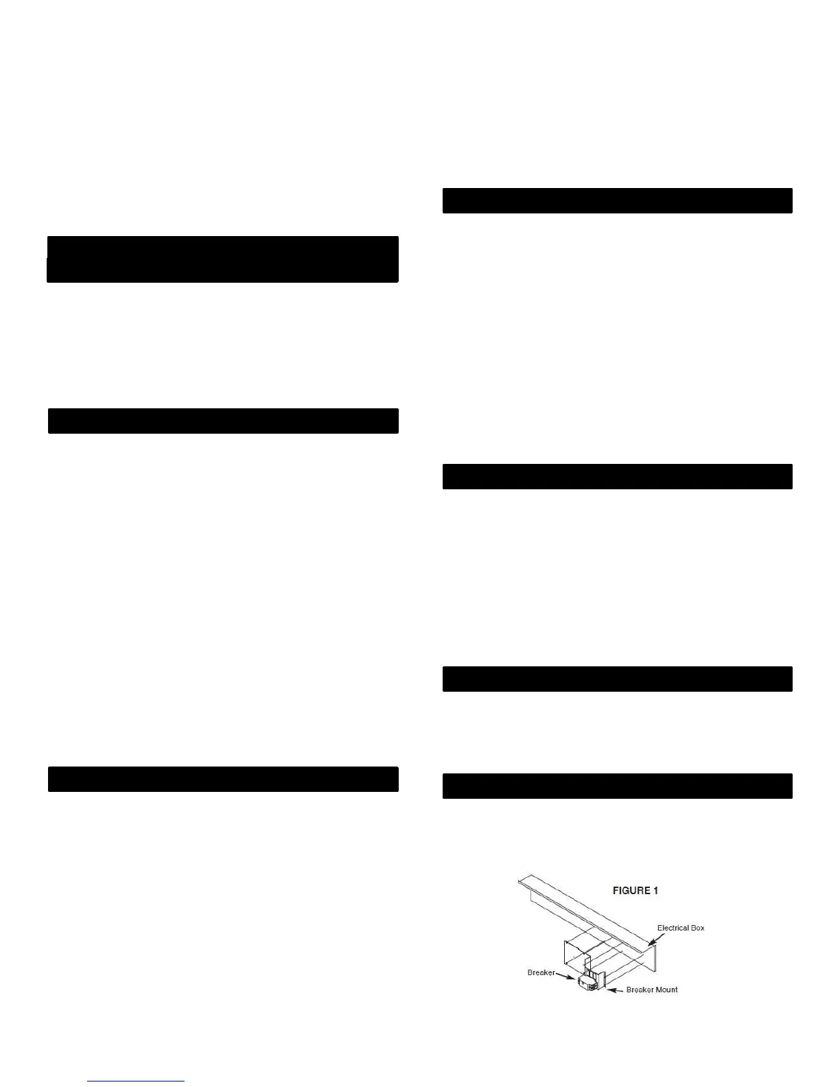
G. BREAKER/DISCONNECT ASSEMBLY
These units are standard equipped from the factory with a unit
disconnect. This is in the form of a circuit breaker (230V models)
or disconnect (460V models). If an optional electric heat kit is to be
installed, follow the instructions included with the heater assembly.
See Figure 1 for reference.
REV. 10/26/16
3
678628-W

 Loading...
