WARNING: ELECTRICAL EQUIPMENT
SHOULD BE INSTALLED BY A QUALIFIED,
LICENSED ELECTRICIAN. IMPROPER
ELECTRICAL HOOK-UP MAY DAMAGE
EQUIPMENT, CAN CREATE A HAZARD AND WILL VOID
WARRANTY.
H. ELECTRICAL HOOKUP
The line voltage electrical service can be routed through the right
side panel, the right side of the back panel, or left side panel. Each
area is supplied with two line voltage knock-outs (1/2" – 3/4" and
1" – 1¼"). Low voltage wiring can be routed through the right or left
side panel.
NOTE: When ro
uting line voltage through the return air
compartment, conduit MUST be used (even though this is a dry
area) to comply with the NEC code. A 1
1
/4" conduit is supplied
for this application. Refer to the ELECTRICAL DATA tables for
minimum wire size and maximum breaker size. All wire sizes listed
under the dual-feed circuit column are based on no more than
three (3) conductors in the same conduit. If two circuits or more
than three (3) conductors are to be routed in the same conduit, the
ampacity of the wire size listed MUST be derated. Refer to Article
310 of the NEC code for adjustment factors. Be sure to install a
ground wire of the proper
s
i
z
e
to the
un
i
t
’
s
e
qu
i
pmen
t ground
l
ug.
I. LOW VOLTAGE WIRING
230 volt, 1- and 3-phase units are equipped with dual-primary
voltage transformers for 208/240 volt operation. These models are
factory wired to the 240 volt tap. For 208 volt operation connect the
factory-installed black wires from the 240 volt tap to the 208 volt
tap. The acceptable voltage range of the tap is as follows.
Tap Voltage Range
240 Volt 253 - 216
208 Volt 220 - 187
Five (5) conductor thermostat wires should be run from the
thermostat location to the unit. Thermostat wire should be sized as
shown on the table below.
Refer to wiring diagrams for connection details.
STAGING OF ELECTRIC HEAT
All V Series units with electric heat assemblies above 10 kW may
be wired for single or two-stage heat. These models come factory
wired for single-stage operation. For two-stage operation, remove
the jumper bar from between the W1 and E terminal. Wire the first-
stage heat to terminal W1. Wire the second-stage heat to terminal
E.
J. UNIT INSTALLATION
V SERIES UNITS ARE FOR USE IN SINGLE-STORY
BUILDI
NGS ONLY
1. As previously stated, the wall that the unit is to be installed
onto MUST be strong enough to support the unit under the
condition for which it will be used. For example, a unit to be
installed on a building that is intended to be transported will
require more wall strength than a unit installed at a
permanent site. Existing walls may need additional
reinforcement. NEVER RELY ON EXTERIOR SIDING OR
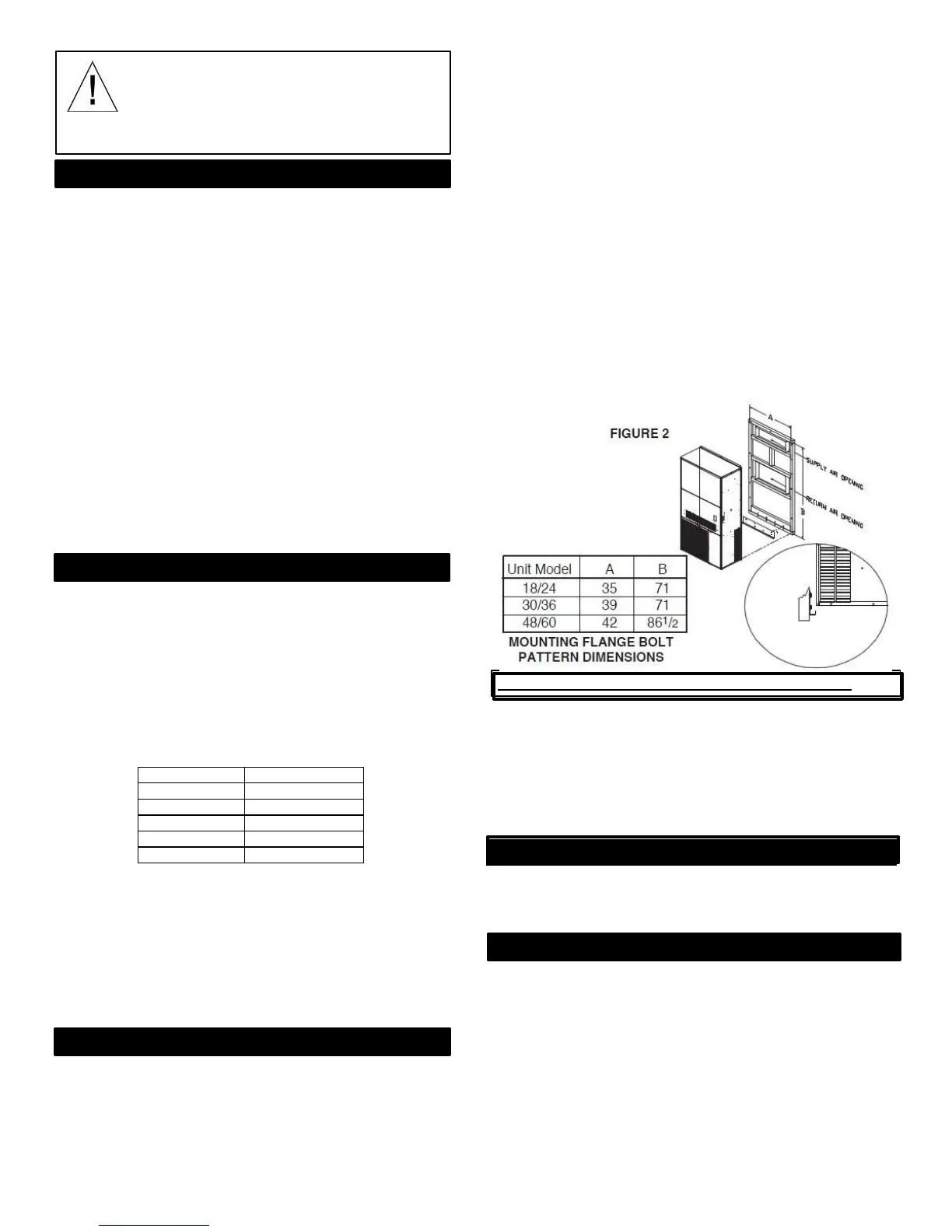
PLYWOOD TO SUPPORT THE UNIT. Figure 2 at right
represents a typical installation of a single-story stud wall at
a permanent site. Since building materials and techniques
vary with regions and intended use, a building contractor
and/or local building code official MUST be consulted for
suitable construction methods.
2. Locate and attach the lower mounting bracket in the
desired location on the building.
3. Apply a suitable amount of caulk or silicone across the
entire length of the top rain flashing and side mounting
flanges.
4. Remove the flanges on both ends of the pallet and slide the
un
i
t
a
pp
r
o
x
i
m
a
t
e
l
y
2
”
off
the rear
of
pallet. Lift unit gently
into location with fork truck, taking care to align unit with
lower mounting bracket.
5. While allowing a small portion of weight on the lower
bracket, push the unit against the wall and fasten
appropriately.
SPECIAL NOTES FOR UNIT INSTALLATION
1) Minimum 12” clearance at the bottom of the unit for
unrestricted airflow.
2)
Ensure the ambient temperature uniformity around unit
3)
Intake and discharge of the outdoor air flow must not be
restricted or altered.
4)
All insulation and sealing related to the installation must
be completed properly
K. CONDENSATE DRAIN
A
3
/
4
”
d
r
a
i
n
hose
i
s
l
oc
a
t
e
d
on the bottom
s
i
d
e
of
the unit. The
drain may be extended for condensate removal to comply with
local codes (use fitting size or larger). Install a condensate trap on
this line.
L. AVAILABLE OPTIONS
Eubank wallmount air conditioners and heat pumps have the
ability to equip a variety of options:
Electric Heat 5-20kW Energy
Recovery Ventilator Sound
Attenuation Module Powered
Ventilation Damper
Low Ambient Packages
Economizer
Lead Lag Controllers
Option kits must be installed according to the respective
installation manual to ensure safe and reliable operation.
Installation manuals are included with the option kit or can be
found on the Eubank website, www.EubankNCC.com.
REV. 10/26/16
4
678628-W
5) External Static pressure should not exceed the minimum
value in the AHRI Standard 390

 Loading...
