5
Operating Instructions
Safety Contact Expansion ESM-TE3..
5. Setting time delay:
Set the desired time delay on the rotary knob and
seal the knob with the supplied sticker. (For xed
time variant ESM-TE3..-05S this step is not required
because a xed time delay of 0.5 seconds is set).
Attention: Tick marks should be regarded only as
a setting aid. Always make sure to measure the
time delay.
6. Starting the device:
Switch the operating voltage on.
Attention: If the Automatic start behavior is set
on the safety relay, the safety contacts will close
immediately.
If the Monitored manual start behavior is set, close
the start button to close the safety contacts.
The LEDs K1 and K2 on the safety relay and on the
ESM-TE3.. illuminate.
7. Activating safety function:
Open the emergency stop circuit by actuating the
connected safety switch. The safety contacts of the
safety relay open immediately; the safety contacts
of the ESM-TE3.. open after the time set on the
rotary knob elapses.
Attention: Measure the time delay.
8. Reactivating:
Close the emergency stop circuit. If Automatic start
is selected on the safety relay, the safety contacts
will close immediately.
If the Monitored manual start behavior is set, close
the start button on the safety relay to close the safe-
ty contacts of the safety relay and the ESM-TE3...
What to do in case of a fault?
Device does not switch on:
f Check the wiring of the ESM-TE3.. and the safety
relay by comparing it with the wiring diagrams (also
see operating instructions for the safety relay).
f Check the safety switch used on the safety relay
for correct function and adjustment.
f Check whether the emergency stop circuit of the
safety relay is closed.
f Check whether the start button on the safety relay
(with manual start) is closed.
f Check the operating voltage at A1 and A2 on the
safety relay and on the ESM-TE3...
f Is the feedback loop closed?
Device cannot be switched on again after an
emergency stop:
f Check whether the emergency stop circuit was
closed again.
f Was the start button opened before closing of the
emergency stop circuit (with manual start)?
f Is the feedback loop closed?
f Is the power supply present during the time
sequence?
If the fault persists, perform the steps listed under
Setup procedure.
If these steps do not remedy the fault either, return
the device to the manufacturer for examination.
Opening the device is impermissible and will
void the warranty.
Maintenance
The device must be checked once per month for
proper function and for signs of tampering and by-
passing of the safety function. Check the wiring of
the device and activate the emergency stop function.
Check the time delay.
The device is otherwise maintenance-free, provided
that it was installed properly.
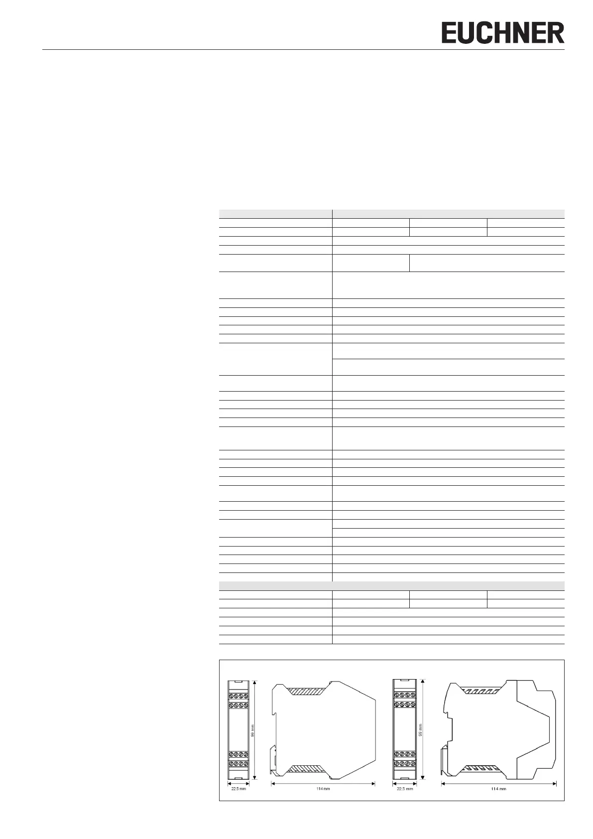
Fixed terminals
Plug-in terminals
Fig. 4: Dimension drawing for ESM-TE3..
Disposal
Pay attention to the applicable national regulations
and laws during disposal.
Declaration of conformity
The product complies with the requirements accord-
ing to Machinery Directive 2006/42/EC.
The EU declaration of conformity can be found at
www.euchner.com. Enter the order number of your
device in the search box. The document is available
under Downloads.
Service
If servicing is required, please contact:
EUCHNER GmbH + Co. KG
Kohlhammerstraße 16
70771 Leinfelden-Echterdingen
Germany
Service telephone:
+49 711 7597-500
E-mail:
support@euchner.de
Internet:
www.euchner.com
Technical data
Parameter Value
Version ESM-TE301 ESM-TE302 ESM-TE303
Operating voltage AC/DC 24 V AC 115 V AC 230 V
Rated supply frequency 50 - 60 Hz
Permissible deviation ± 10%
Power consumption DC 24 V AC 230 V
Approx. 1.5 W Approx. 4.0 VA
Time delay
ESM-TE3.. 1…30s, continuously adjustable
ESM-TE3..-05S 0.5s, xed
Control voltage at S11 DC 24 V
Control current S11…S14 Approx. 40 mA
Safety contacts 3 NO contacts
Monitoring contacts 1 NC contact (monitoring contact for safety relay)
Max. switching voltage AC 250 V
Safety contact breaking capacity
(17-18, 27-28, 37-38)
AC: 230 V, 1,500 VA, 6 A for ohm resistive load
230V, 4A for AC-15
DC: 24 V, 30 W, 1.25 A for ohm resistive load
24V, 2A, for DC-13
Max. cumulative current of all safety
contacts
10.5A
Minimum contact load 24 V, 20 mA
Contact fuses 6 A gG
Conductor cross-section 0.14 - 2.5 mm²
Tightening torque (min./max.) 0.5Nm/0.6Nm
Typ. switch-on delay/switch-off delay for
the normally open contacts upon demand
from the safety circuit
<60 ms / <50 ms
Max. length of control line 1,000 m with 0.75 mm²
Contact material AgNi
Mech. contact life Approx. 1 x 10
7
Test voltage 2.5 kV (control voltage/contacts)
Rated impulse withstand voltage, leakage
paths/air gaps
4 kV (DIN VDE 0110-1)
Rated insulation voltage 250 V
Degree of protection IP20
Temperature range DC24V: -15°C to +60°C
AC230V/115V/24V: -15°C up to +40°C
Installation altitude ≤2000m (above sea level)
Degree of contamination 2 (DIN VDE 0110-1)
Overvoltage category 3 (DIN VDE 0110-1)
Weight Approx. 230 g
Mounting Mounting rail acc. to ENIEC60715 TH35
Characteristics according to EN ISO 13849-1 for all variants of the series ESM-BA3
1)
Load (DC-13; 24V) ≤0.1A ≤1A ≤2A
n
op
≤400,000 cycles ≤73,000 cycles ≤17,000 cycles
T
10D
20 years
Category 3
PL d
PFH
D
1.03x10
-7
1/h
1) Additional data can be requested from the manufacturer for applications that deviate from these conditions.
 Loading...