4
Operating Instructions
Safety Contact Expansion ESM-TE3..
Scope
These operating instructions apply to all safety con-
tact expansions ESM-TE3...V1.1.X. These operating
instructions, the document Safety information and
any available data sheet form the complete user
information for your device.
Important!
Make sure to use the operating instructions
valid for your product version. Please contact the
EUCHNER service team if you have any questions.
Supplementary documents
The overall documentation for this device consists
of the following documents:
Document title
(document number)
Contents
Safety information
(2525460)
Basic safety information
Operating instructions
(2090075)
(this document)
www
Declaration of con-
formity
Declaration of conformity
www
Any additions to the
operating instructions
Take any associated additions to
the operating instructions or data
sheets into account.
www
Important!
Always read all documents to gain a complete
overview of safe installation, setup and use of
the device. The documents can be downloaded
from www.euchner.com. For this purpose, enter
the doc. no. or the order number for the device
in the search box.
Correct use
The ESM-TE3.. is an expansion module that can be
operated with any safety relay from the EUCHNER
ESM series, e.g. ESM-BA2.. or ESM-BA3.., in order
to permit delayed switch-off of machine parts. This
could be the case if it is safer to return a tool to
its initial position rst instead of stopping operation
immediately, for example. The ESM-TE3.. was de-
signed as a component for a modular system: any
combination of ESM-TE3.. units and non-time-delayed
contact expansions ESM-ES3.. can be interconnect-
ed with just a few lines, permitting realization of an
overall system with different times and the specic
number of safety contacts required.
Before the device is used, a risk assessment must
be performed on the machine, e.g. in accordance
with the following standards:
f ENISO13849-1
f ENISO12100
f ENIEC62061.
Correct use includes observing the relevant require-
ments for installation and operation, particularly
based on the following standards:
f ENISO13849-1
f ENIEC60204-1
f ENIEC62061.
Important!
f The user is responsible for the integration of the
device in a safe overall system. For this purpose,
the overall system must be validated, e.g. in
accordance with ENISO13849-1.
f The device user must assess and document
remaining risks.
f If a data sheet is included with the product, the
information on the data sheet applies.
Safety precautions
WARNING
f Installation and setup of the device must be
performed only by authorized personnel.
f Observe the country-specic regulations when
installing the device.
f The electrical connection of the device is only
allowed to be made with the device isolated.
f The wiring of the device must comply with the
instructions in these operating instructions,
otherwise there is a risk that the safety function
will be lost.
f It is not allowed to open the device, tamper with
the device or bypass the safety devices.
f All relevant safety regulations and standards are
to be observed.
f The overall concept of the control system in
which the device is incorporated must be vali-
dated by the user.
f Failure to observe the safety regulations can re-
sult in death, severe injuries and serious damage.
f Note down the version of the device (see type la-
bel Vx.x.x) and check it each time prior to setup.
If the version changes, the use of the device in
the overall application must be validated again.
Features
f 3 safe, redundant, time-delayed relay outputs
1 auxiliary contact (error monitoring)
f Control via safety relay from the EUCHNER ESM
series
f Continuously adjustable time delay (1…30s) or
xed time delay (ESM-TE3...-05S)
f Modular, freely congurable safety system
f Error monitoring by safety relay
f Indication of the switching state via LED
f Up to PLd, category3, SILCL2
Function
The time-delayed safe expansion module ESM-TE3..
in combination with a safety relay from the EUCHNER
ESM series is designed for the safe isolation of
safety circuits according to ENIEC60204-1 and can
be used up to safety category3, PLd according to
EN ISO 13849-1.
The ESM-TE3.. provides a control voltage of DC24V
at terminal S11. In order for the ESM-TE3.. to switch
together with the connected safety relay, the control
voltage at S11 is connected to terminals S15 and
S16 of the ESM-TE3.. via one of the safety contacts
of the safety relay (see Fig. 5 and Fig. 6). The safety
contacts of the safety relay close when the safety
relay is activated, and the DC24V control voltage
from terminal S11 is then at terminals S15 and S16
of
the
ESM-TE3... The safety contacts of the ESM-TE3..
switch immediately.
The safety relay disconnects the control voltage
and the safety contacts in the ESM-TE3.. open after
the time set on the ESM-TE3.. elapses (the power
supply must be available during this time) if there is
demand for the safety function from the emergency
stop circuit (e.g. safety door opened).
If a fault occurs in the ESM-TE3.., this is detected by
the safety relay via terminals S25 and S26.
Independent operation without a safety relay
is not possible.
Fig. 1: Block diagram for ESM-TE3..
Mounting
As per ENIEC60204-1, the device is intended for
installation in control cabinets with a minimum de-
gree of protection of IP54. It is mounted on a 35mm
mounting rail according to ENIEC60715TH35.
Fig. 2: Mounting/removing
Electrical connection
f When the 24 V version is used, a safety trans-
former according to ENIEC61558-2-6 or a power
supply unit with electrical isolation from the mains
must be connected.
f External fusing of the safety contacts must be
provided.
f A maximum length of the control lines of 1,000 m
with a conductor cross-section of 0.75mm² must
not be exceeded.
f The conductor cross-section must not exceed
2.5mm².
f If the device does not function after setup, it must
be returned to the manufacturer unopened. Open-
ing the device will void the warranty.
f A suppressor circuit suitable for inductive loads
(e.g. free-wheeling diode) is to be provided.
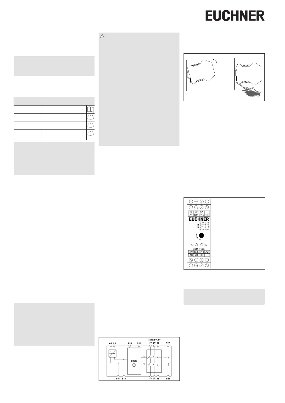
A1 Power supply
A2 Power supply
S11 DC24V control voltage
S10 Control line
S15 Control line
S16 Control line
S25 Error monitoring
S26 Error monitoring
17-18 Time-delayed safety contact 1
27-28 Time-delayed safety contact 2
37-38 Time-delayed safety contact 3
Fig. 3: Connections
Setup procedure
Notice
The items listed under Electrical connection must
be observed during setup.
1. Wiring ESM-TE3..:
Wire the ESM-TE3.. with the EUCHNER safety relay
according to your application (see Fig. 5 and Fig. 6).
2. Wiring safety relay:
Wire the safety relay according to the required
Performance Level determined (see operating
instructions for the safety relay).
3. Wiring feedback loop:
Wire the feedback loop as shown in the examples
in Fig. 7 and Fig. 8.
4. Wiring power supply:
Connect the power supply to terminals A1 and A2
(see Fig. 9).
Attention: Wiring only in de-energized state.
 Loading...