Operating Instructions
Safety Contact Expansion ESM-TE3..
6
Subject to technical modications; no responsibility is accepted for the accuracy of this information. © EUCHNER GmbH + Co. KG 2090075-13-04/24 V1.1.0 (translation of the original operating instructions)
Applications
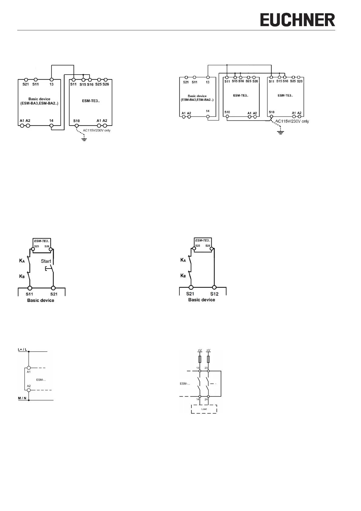
Depending on the application, the device must be wired with an EUCHNER safety relay as shown in Fig. 5 and Fig. 6.
Wiring
Fig. 5: Connection of ESM-TE3.. to safety relay
Wiring of the ESM-TE3.. via only 4 lines:
A safety contact of the safety relay (e.g. 13-14) activates the relays of the
ESM-TE3.. (S11 and S15 / S16).
Two lines on S25 and S26 are required for feedback/error monitoring. This is
to be wired, depending on the application, as per Fig. 7 or Fig. 8.
An error in the ESM-TE3.. thereby prevents the entire safety chain from restart-
ing. Earth faults in the control lines are detected in addition to internal faults.
Fig. 6: Connection of several ESM-TE3.. units to safety relay
If further ESM-TE3.. units are to be integrated into the system, terminals
S11 must be connected in parallel on all ESM-TE3.. units. This also applies
to terminals S10 and terminals S15 / S16.
The feedback loops (S25-S26) for the individual expansion devices must be
connected in series with the start for the safety relay (cf. Fig. 7 or Fig. 8).
Notice:
In order to activate ground fault monitoring, S10 must be connected to PE (protective earth) on the AC115/230V devices. With AC/DC24V, connect PE
only to the power supply unit according to ENIEC60204-1.
Feedback loop
Fig. 7: Feedback loop.
Contactors connected to the ESM-TE3.. or the safety relay are monitored via the
feedback loop of the safety relay. KA and KB are the positively driven contacts
of the connected contactor or expansion module.
Fig. 8: Feedback loop with automatic start.
Contactors connected to the ESM-TE3.. or the safety relay are monitored
via the feedback loop of the safety relay. KA and KB are the positively driven
contacts of the connected contactor or expansion module.
Power supply and safety contacts
Fig. 9: Connection of the power supply to terminals A1 and A2 (power supply
according to the technical data).
Fig. 10: Connection to switching loads on safety contacts (example
contact conguration. Differing according to device type.
Switching voltages +V corresponding to technical data).
 Loading...