9
Operating Instructions
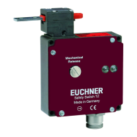
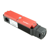
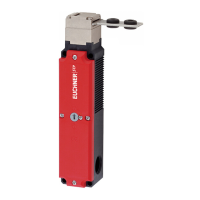
Safety Switch STP…
With auxiliary key release
76,5
20,5
19
Direction of rotation
Marking
Lock function
Type Lock
Key removable
in position
STP…C1844 Identical locking
and
Figure 2: Dimension drawing for STP… without insertion funnel and STP… with insertion funnel
35,5
45,5
30
4
9
16
4
0,5
0,5
v
19
19
4
L
Actuating head with insertion funnel
M = 0.8 Nm
Necessary minimum travel + permissible overtravel
Approach direction
Actuator S
standard
Actuator L
insertion funnel
Horizontal (h) 24.5 + 5 28.5 + 5
Vertical (v) 24.5 + 5 28.5 + 5
With escape release (short/long actuator shaft)
61,5
74,7
67,5
53
36
4
∅14
20
31
M4
Short actuator shaft
Long actuator shaft
Always install the escape
release lever on the
recessed side
Establish a positive
connection between the
shaft and lever.
With escape release (rotary knob)
Key to symbols
/
Guard locking ready for operation
/
Guard locking released
With plug connector SR11
30
Locking screw
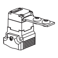
Auxiliary release
Auxiliary release with triangu‑
lar wedge
(two triangular keys included)
)x3( 5,1x02M
30
<40>
441
5,53
5,14
30
4
22
16
<42>
0,5
v
For M5 > 35 mm
ISO 1207 (DIN84)
ISO 4762 (DIN912)
M = 1.5 Nm
M = 0.8 Nm
green
red
Only for switches with cable
entry:
LED module enclosed sep‑
arately.
Observe assembly instructions.
1000
26
33
With wire front release