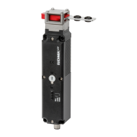
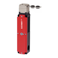
Operating Instructions TZ... Safety Switch
EUCHNER GmbH + Co. KG Kohlhammerstraße 16 D-70771 Leinfelden-Echterdingen Tel. +49/711/75 97-0 Fax +49/711/75 33 16 www.euchner.de info@euchner.de
Subject to technical modifications; no responsibility is accepted for the accuracy of this information. © EUCHNER GmbH + Co. KG 088062-07-12/10 (translation of the original operating instructions)
1
6
5
4
3
2
911
10
54
63
72
81
7
8
9
10
11
17
16
15
18
1
2
3
4
5
14
13
6
19
12
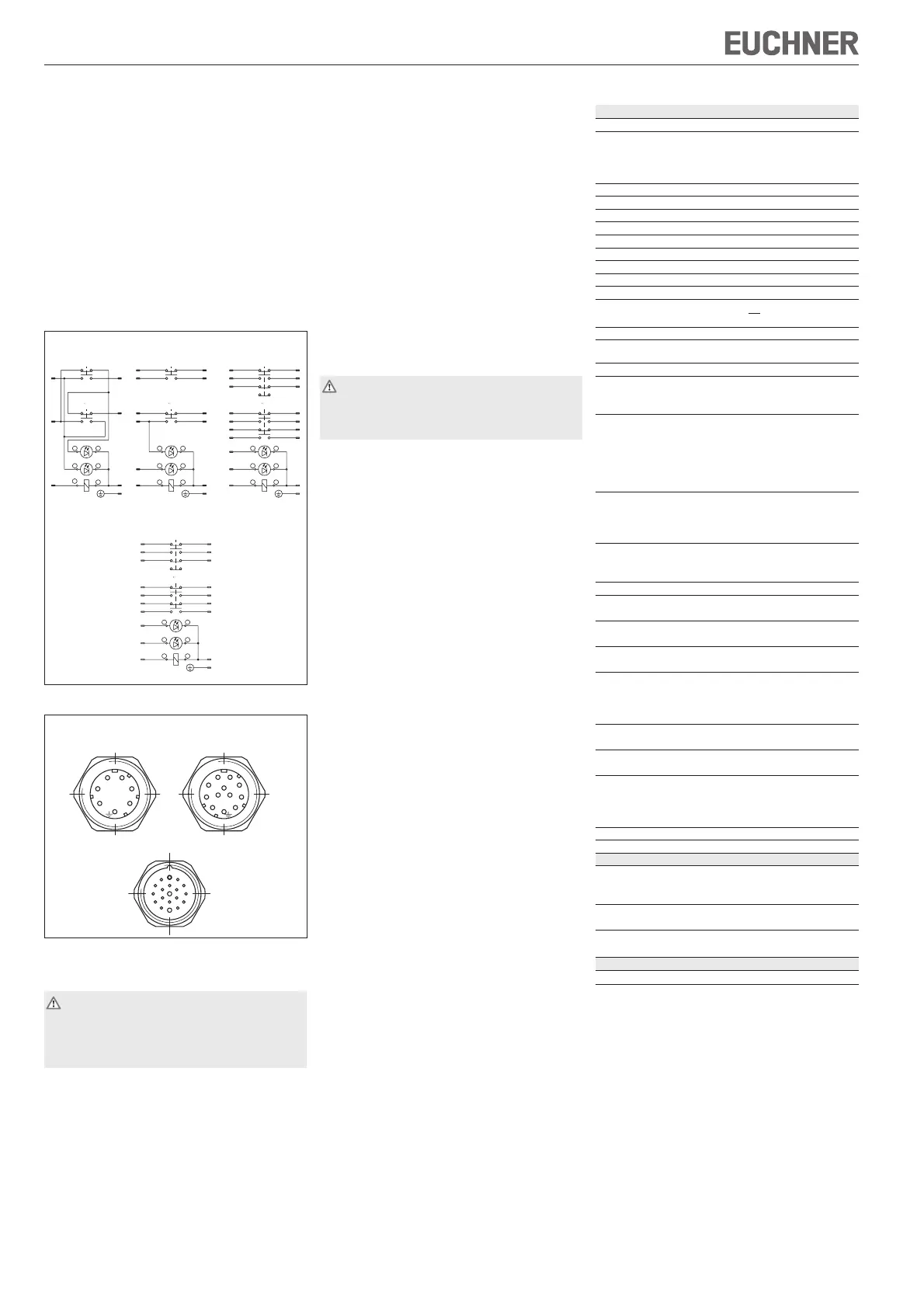
View on the connection side of the safety switch
TZ..RC18
TZ..SR6 TZ..SR11
Fig. 2b: Connector assignment
(F
Zh
=
F
max
) = 1500 N
1.3
f Version TZ.. with cable entry
f
TZ..M: Fit cable gland M20 x 1.5 with appropriate
degree of protection.
f
For terminal assignment see Figure 2a.
f
Tighten screws for connections to the switching
element to 0.5 Nm.
f
Tighten the connection terminals with a torque of 0.5 Nm.
f
Check that the cable entry is sealed.
f
Close switch cover and tighten screws to 1.2 Nm.
f
Fit sealing to the mechanical release using the parts
supplied to prevent usage of the mechanical release
during operation.
f Version TZ..SR, TZ..RC18 and TZ..RC18...C1826
(plug connector)
f
For connector assignments see Figure 2a-2b.
PE
3
1
1413
21 22
62
UK
SK
13
21 22
14 14
2221
13
4
3
5
6
LED
RD
2
1
16
15
41
33
42
34
14
87
13
10
2221
13 14 1817
9
3
1211
21 22
6
LED GN
5
4
PE/12
11
12
19
UK
SK
34
42
33
41
SK
UK
3
86
9
PE
4
2
LED GN
2221
13 14
11
10 1
7
5
1
2
LED RD
65
34
4
3
56
LED RD
21
LED GN
5
4
Illustration: Safety guard closed, actuator locked
TZ..SR6 TZ..SR11 TZ..RC18
4
3
5
6
LED
RD
2
1
16
15
41
33
42
34
14
87
13
10
2221
13 14 1817
9
3
1211
21 22
4
LED GN
19
6
PE/12
11
12
5
UK
SK
34
42
33
41
TZ..RC18...C1826
Fig. 2a: Terminal assignment
f Electrical function test
1. Switch on operating voltage.
2. Close all safety guards.
Guard locking by solenoid force: ¨ Activate
guard locking.
f
The machine must not start automatically.
f
It must not be possible to open the safety guard.
3. Enable operation in the control system.
f
It must not be possible to deactivate the guard locking
as long as operation is enabled.
4. Disable operation in the control system and
deactivate guard locking.
f
The safety guard must remain locked until there is no
longer any risk of injury.
f
It must not be possible to start the machine as long as
the guard locking is deactivated.
Repeat steps 2 - 4 for each safety guard.
Inspection and service
If damage or wear is found, the complete switch
and actuator assembly must be replaced.
Replacement of individual parts or assemblies is
not permitted!
No servicing is required, but regular inspection of
the following is necessary to ensure trouble-free long-
term operation:
f
correct switching function
f
secure mounting of components
f
dirt and wear
f
sealing of cable entry
f
loose cable connections or plug connectors.
Note:The year of manufacture can be seen in the bottom,
right corner of the rating plate.
Exclusion of liability under the following
circumstances
f
incorrect use
f
non-compliance with safety regulations
f
non-compliance with safety regulations
f
failure to perform functional checks.
EC declaration of conformity
The manufacturer named below herewith declares that
the product fulfills the provisions of the directive(s) listed
below and that the related standards have been applied.
EUCHNER GmbH + Co. KG
Kohlhammerstraße 16
70771 Leinfelden-Echterdingen, Germany
Directives applied:
f Machinery directive 2006/42/EC
Standards applied:
f EN 60947-5-1:2004 + Cor.:2005 + A1:2009
f EN 1088:1995+A2:2008
Leinfelden, July 2010
Dipl.-Ing. Michael Euchner
Director
Duc Binh Nguyen
Authorized representative empowered to draw up
documentation
The signed EC declaration of conformity is included
with the product.
Technical data
Parameters Value
Housing material Anodized die-cast alloy
Degree of protection acc. to IEC 60529
Cable entry IP67
Plug connector IP65
(SR6/SR11/RC18) (with tightened mating connector)
Mech. operating cycles 1 x 10
6
Ambient temperature -25 °C ... +80 °C
Installation position Any
Approach speed 20 m/min
Actuation frequency 1200/ h
Actuating force at 20 °C 35 N
Extraction force 30 N
Retention force 10 N
Locking force F
max
2000 N
Locking force F
Zh
in acc. with GS-ET-19
Weight approx. 1.2 kg
Switching principle Slow-action switching contact
Contact material Silver alloy, gold flashed
Connection type
TZ..M Screw terminals M20 x 1.5
TZ..SR6/SR11/RC18 Connector
Connection cross-section (rigid/flexible)
TZ..M 0.34 ... 1.5 mm
2
For mating connector SR6 (0.5-1.5) mm
2
SR11 0.5 mm
2
RC18 19x(0.75-1.0) mm
2
RC18..C1825 16x(0.38-0.5), 3x(0.75-1.0) mm
2
Rated insulation voltage
TZ..M, TZ..SR6 U
i
= 250 V
TZ..SR11 U
i
= 50 V
TZ..RC18 U
i
= 110 V
Rated impulse withstand voltage
TZ..M, TZ..SR6 U
imp
= 2.5 kV
TZ..SR11, TZ..RC18 U
imp
= 1.5 kV
Rated short-circuit current 100 A
Degree of contamination
(external, acc. ?to EN 60947-1)
3 (industrial)
Switching current, min.,
at 24 V
1 mA
Switching voltage, min.,
at 10 mA
12 V
Utilization category to IEC 60947-5-1
TZ..M, TZ..SR6 AC-15 4A 230V / DC-13 4A 24V
TZ..SR11 AC-15 4A 50V / DC-13 4A 24V
TZ..RC18 AC-15 4A 110V / DC-13 4A 24V
Conventional
thermal current I
th
4 A
Short circuit protection
according to IEC 60269-1
4 A gG
Solenoid operating voltage
TZ..024 AC/DC 24 V (+10%/-15%)
TZ..110 AC 110 V (+10%/-15%)
TZ..220 AC 230 V (+10%/-15%)
Solenoid duty cycle 100 %
Solenoid power consumption 10 W
Limitations at ambient temperature above +70 ... +80 °C
Utilization category
TZ..SR6 AC-15 2A 230V / DC-13 2A 24V
TZ..SR11 AC-15 2A 50V / DC-13 2A 24V
Conventional
thermal current I
th
2 A
Short circuit protection
to IEC 60269-1
2 A gG
Reliability figures according to EN ISO 13849-1
B
10d
3 x 10
6
Functional check
Warning! Danger of fatal injury as a result of faults
in installation and functional check.
Before carrying out the functional check, make sure
that there are no persons in the danger area.
Observe the valid accident prevention regulations.
After installation and any fault, the safety function must
be fully checked. Proceed as follows:
f Mechanical function test
The actuator must slide easily into the actuating head.
Close the safety guard several times to check the
function.
 Loading...