6 7
Doubler Specific Features
In addition to all of the innovative
features found on the Micro, the Doubler
adds some specific features designed for
the upright/acoustic player.
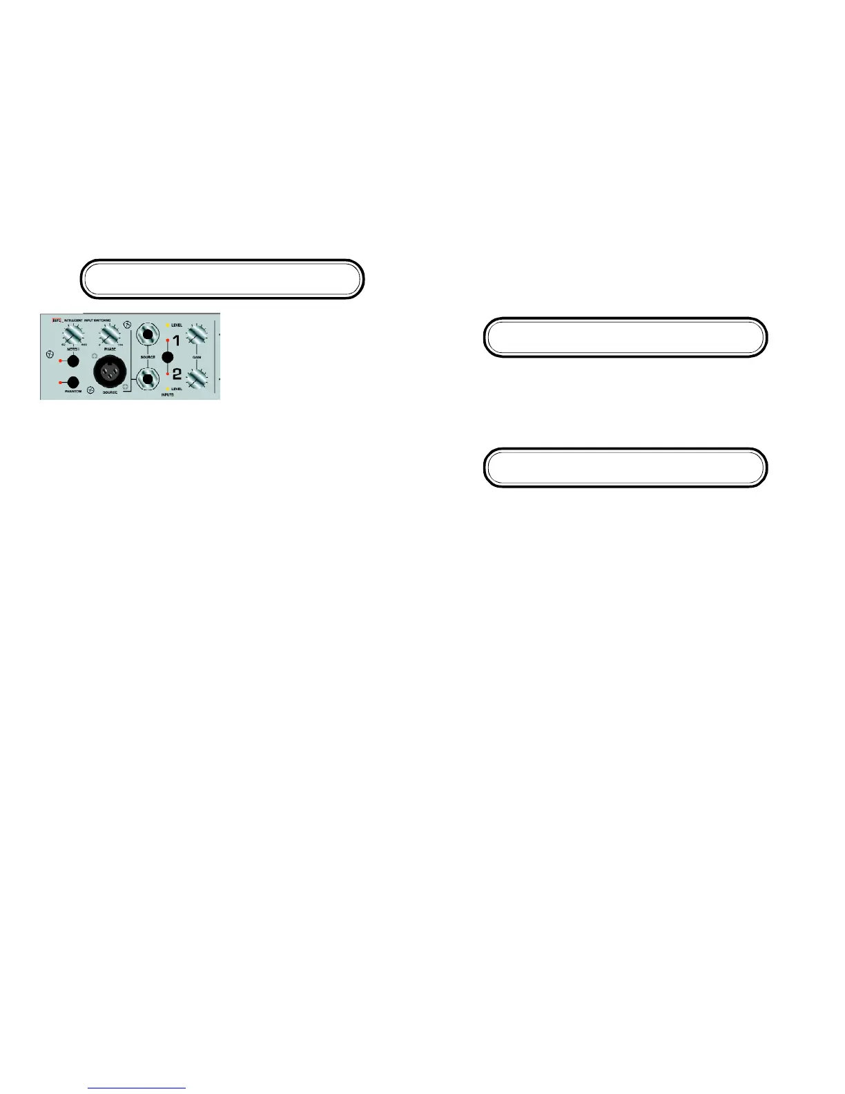
Notch Filter: To help with feeback, the
Doubler has a variable Notch Filter. The
Notch Filter attenuates the signal 15db from 50 to 600K at .05 octavees. THE NOTCH
FILTER IS ONLY AVAILABE ON CHANNEL 2.
Microphone Input with Phantom Power: The Doubler has a Low Impedance Micro-
phone input with selectable 48v Phantom Power.
Phase Control: The Doubler features an innovative 180 degree sweepable phase
control to adjust the phase between Channel 1 and Channel 2. This control only
works when BOTH Channel 1 and Channel2 inputs are being used.
PLEASE NOTE: If you want to use a single input and switch between 2 different EQ
settings (i.e. clean/solo) you MUST use Channel 2 as your “Master” channel
(DOUBLER ONLY).
Some Words from EA Artist Mike Arnopol
The phase control can be useful when combining a pickup and a microphone or two
pickups. Anytime two different pickups or a pickup and a microphone are combined
there are phase interactions between the two. This can result with degrees of
cancellation at different frequencies. Typical phase controls can only reverse the
phase at one position. (180 degrees) The variable phase control on the Doubler offers
the flexibility to alter the phase from 0 degrees (fully counterclockwise) to 180 degrees
(fully clockwise). Experimentation is necessary to find the best sound. No two pickup
or microphone sources react the same when combined, but for the first time one is
able to fine tune the “sweet spot”. Please note that changes in the eq settings can
alter the phase relationships also. Bottomline—experiment with the eq and phase
settings to find the best sound.
The Doubler offers a high quality microphone input. This can accommodate any low
impedance dynamic microphone or a condenser microphone that requires phantom
power. (48 volts). The phantom power switch should be in the “off” position unless
using a microphone requiring phantom power.
The notch filter on channel 2 is useful in eliminating feedback, especially when using
a microphone. A notch filter attenuates a very narrow frequency range (typically not
wider than one note). To use it, raise the volume on channel 2 until feedback begins
to occur. Then turn on the notch switch and rotate the knob until the feedback is
eliminated.
Tone Shaping
The iAMP®Micro and Doubler features a simple yet extremely musical, 3 Band EQ.
The elegant design and pristine sound of the 3 band tone shaping of the Micro and
Doubler allows for a totally neutral sound when set flat. Each band can add +/- 12dB
of gain on each channel. The low and high are shelving and the mid control is
centered around 600hz on Channel 1 and 800hz on Channel 2.
Output Section
Main Control: Adjusts the level going into the power amplifier section. The iAMP
Micro and Doubler was designed to be exceptionally clean, accurate and versatile. If
you want a “dirtier” overdriven-type sound, it is best to use an effects device
through the Effects loop.
DI Output Level: Accessed via the trim pot on the top of the amp, DI Output Level
adjusts the level of the DI, for finer control of levels going to an external mixing board
or recording device. The factory setting should be fine for most applications..
Post/Pre EQ: Configured via internal jumpers, the DI EQ can be set to send either a
clean (PRE) or colored (POST) signal created in the Tone Shaping section. See “A
Look Inside” for specific jumper settings.
Mute Switch: Configured via internal jumpers, The Mute Switch can be configured to
mute the DI and/or the Effects/Tuner Send in addition to the speaker out. The Mute
Switch can be accessed via the front panel switch or with an optional footswitch.
The red mute LED will illuminate if the Micro or Doubler is muted. Please note the amp
is muted at power on.
DI Output Jack: Balanced DI output for sending a balanced signal directly to low
noise studio equipment. The DI can be configured to either Pre (default) or Post EQ
via internal jumper settings. See “A Look Inside” for specific jumper settings. NOTE:
The DI out is a balanced output. A 1/4” stereo jack is used as opposed to a more
common XLR for space considerations. To connect to an XLR input a simple adapter
is needed (rather than an adapter/transformer). The 1/4” stero jack is wired as follows:
Tip=Positive, Ring=Negative, Sleeve=Common.
 Loading...