Do you have a question about the EURA DRIVES E800 series and is the answer not in the manual?
Covers essential safety instructions, warnings, and pictograms for safe operation.
Provides guidelines for safe handling, storage, and cabinet mounting of the inverter.
Details on proper electrical wiring, grounding, insulation, and resistor connections.
Recommendations for adequate installation to ensure electromagnetic compatibility (EMC).
Additional information regarding UL mark requirements and compliance.
Explains the structure of product model names and available options.
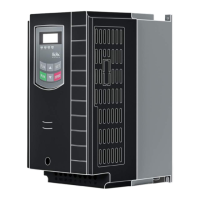
Details the physical build, framesizes, and visual aspects of the inverters.
Comprehensive table of technical specifications for the E800 inverter series.
Lists the product range categorized by framesize, power, and specifications.
Specific instructions for mounting the inverter vertically within a cabinet.
Information regarding the maintenance needs and service intervals for the inverter.
Diagrams and details for power terminal connections across different models.
Guidelines for connecting and selecting appropriate brake resistors.
Recommended cable sizes, fuses, terminal torques, and grounding methods.
Diagrams illustrating control board configurations for different inverter sizes.
Setup and function mapping for digital input and output channels.
Configuration details for analogue input and output channels.
Explanation of the display segments, status LEDs, and their meanings.
Guide to using the keypad buttons for control, navigation, and parameter access.
Lists common display codes for parameters, settings, and error messages.
Instructions for connecting and using the optional remote operating panel.
Steps for navigating, changing, and saving parameter values.
Explanation of parameter types: read-only, dynamic, and static.
Configuration of fundamental parameters like password, frequency, and ramps.
Defines parameters for creating a user-specific V/Hz curve for motor control.
Step-by-step guide to restore the inverter to its factory default settings.
Configuring start, stop, and motor rotation direction using various sources.
Options for selecting primary speed reference sources like internal, analogue, or keypad.
Methods for combining primary and secondary speed references for control.
Setup for two-wire and three-wire control methods for start/stop and rotation.
Assigns specific functions to digital output channels.
Assigns specific functions to digital input channels.
Tables for selecting fixed frequencies and acceleration/deceleration ramps.
Configuring analogue inputs for speed reference signals.
Assigning non-linear curves to analogue input channels.
Configuration of analogue output channels for signals like frequency or current.
Selecting between different modes for fixed frequency operation.
Parameters for setting up automatic cycling of frequencies and sequences.
Configuration settings for the DC-Brake function.
Functions to limit current and voltage for protection.
Configuration for brake chopper and 'Catch on the fly' motor control.
List and explanation of error codes and historical fault data.
Settings for phase-loss, voltage, temperature, and overcurrent monitoring.
Configuration of fan control modes and motor/inverter overload protection.
Procedures for automatic measurement and storage of motor parameters.
Additional parameters for permanent magnet motor (PMM) control.
Configuration of inverter address, interface mode, parity, and baudrate.
Wiring diagrams for MODBUS communication hardware connections.
Configuring set-point, feedback channels, and controller limits.
Settings for proportional, integral, derivative gains, and dead band.
Configuration of sleep mode and emergency functions.
Tools for monitoring the status of digital inputs.
Checking analogue input values and stimulating analogue outputs.
| Brand | EURA DRIVES |
|---|---|
| Model | E800 series |
| Category | DC Drives |
| Language | English |