Do you have a question about the Eurapo Sigma SV and is the answer not in the manual?
Describes the heating, cooling, and dehumidification uses of fan coils.
Explains the working principle of fan coils, including heating and cooling.
Details factors influencing fan coil thermal performance and optimization.
Lists critical operational limits for safe and effective fancoil use.
Lists the different EURAPO fancoil models covered in the manual.
Mentions EURAPO's software for selecting the correct fan coil size.
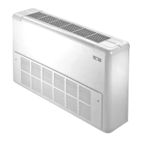
Details vertical Sigma SV and SV/AF units with cabinets.
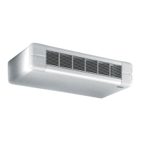
Details horizontal Sigma SH and SH/AF units with cabinets.
Describes vertical Prisma PV and PV/AF units with cabinets.
Details horizontal Prisma PH and PH/AF units with cabinets.
Covers the low-height SVR model from the Low Body series.
Provides visual guidance on recommended fancoil installation methods.
Details concealed CV and CV/AF units without cabinets.
Describes concealed CH and CH/AF units without cabinets.
Covers the low-height CVR model from the Low Body series.
Offers visual guidance for suggested installation of concealed units.
Describes the inner frame construction and materials.
Details the construction and specifications of the fancoil coils.
Explains the fan deck assembly, motor, and impellers.
Covers the electrical panel, terminal board, and wiring diagrams.
Describes the type, cleaning, and placement of the air filter.
Details the unit's external casing, material, color, and grilles.
Describes the CBL10 electrical box for valve connections.
Details the CBL20 electrical box for heaters or fan speed control.
Explains the CBL30 electrical box for valves and fan speed control.
Describes the KREL electric heater and its safety features.
Details fan speed selectors for controlling fan speeds only.
Describes the TAD10 wall-mounted room thermostat.
Explains CML and CMR room thermostats with speed selection.
Details advanced electronic controllers with microprocessor.
Introduces the OMNIBUS digital system for integrated fancoil management.
Describes the OPV10 card for BMS integration and regulation.
Details the OC236 display console for unit operation and service.
Describes the OC736 analogue plus console for unit control.
Explains the IR receiver and remote control for user regulation.
Covers centralized management via OMNIBUS supervision systems.
Details the OC436 manager console for controlling multiple units.
Describes the OTOUCH unit for advanced supervision and management.
Explains the OCB50 webserver for large-scale fancoil management.
Details the TM thermostat for preventing fan operation in low temperatures.
Describes the WS water sensor for automatic Summer/Winter switchover.
Details the AS air sensor for fancoil intake air measurement.
Explains the CS check sensor for air outlet monitoring and fault detection.
Covers the AFT thermostat for anti-frost protection.
Describes the PC condensate pump for water discharge.
Details ON/OFF regulating valves with thermoelectric actuators.
Describes modulating regulating valves with modulating actuators.
Explains the DT shut-off ball valve for system separation.
Details the compact kit for four-pipe systems with 3-way valves.
Describes the FY water filter with a stainless steel element.
Details the painted steel feet for unit support and cable covering.
Describes the long socle with feet for vertical air intake accessories.
Explains the vertical back panel for units with visible backs.
Details the horizontal back panel for units with visible backs.
Describes the vertical external air intake with manual damper.
Details the vertical external air intake with motorized damper.
Describes the horizontal external air intake with manual damper.
Details the horizontal external air intake with motorized damper.
Explains the horizontal external air intake for bottom air intake units.
Describes the air delivery plenum for connecting to air ducts.
Details the 90° air delivery plenum for duct connection.
Describes the air suction plenum for external air intake.
Explains the air suction plenum with spigots for duct connection.
Details the 90° air suction plenum for external air intake.
Describes the RCA duct connection for suction air ducts.
Details the telescopic connection for air outlet.
Explains the telescopic connection for air intake with G3 filter.
Describes the air outlet grill for RCCMF connection.
Details the air intake grill for RCCAF connection.
Provides nominal and static pressure air volume data for fan speeds.
Lists air volume specifications for Sigma, Prisma, and Concealed series.
Provides air volume specifications for the Low Body series.
Presents cooling capacity data for different fan speeds and sizes.
Details cooling capacities for Sigma, Prisma, and Concealed units.
Lists cooling capacities for Low Body series units.
Presents heating capacity data for various fan speeds and sizes.
Details heating capacities for Sigma, Prisma, and Concealed units.
Lists heating capacities for Low Body series units.
Provides electrical data including power consumption and current.
Defines sound power as total radiated energy from a source.
Explains sound pressure and factors affecting noise perception in a room.
Wiring diagram for the CBL00 electrical box.
Wiring diagram for CBL00 with EVC/EVH valve control.
Wiring diagram for CBL10 with EVCM/EVHM valve control.
Wiring diagram for CBL20 in Master/Slave configuration.
Wiring diagram for CBL20 with RE regulator.
Wiring diagram for CBL30 with EVCM/EVHM valve control.
Wiring diagram for CBL00 with EV and PC components.
Wiring diagram for CBL00 with EVC/EVH and PC components.
| Brand | Eurapo |
|---|---|
| Model | Sigma SV |
| Category | Air Conditioner |
| Language | English |