Eurekazone, LLC 1904 NE Jacksonville Rd Ocala, FL 34470
Phone (352) 620-2262 Fax (352) 620-2576 Techsupport@eurekazone.com www.eurekazone.com
FRAME ASSEMBLY
The first stage of assembly involves putting together the bench frame. The diagrams for each step show the
frame in the upright position but for ease of assembly it may be assembled upside down on a workbench. The
following is the list of parts needed to assemble the bench frame:
(2) – 48.25” SSME Side Rails Part A
(2) – 22.5” SSME End Rails Part B
(2) – Corner Sets With Connectors Part L
(2) – 38.25” Side Support Bracket Part E
(2) – 38.25” Side Support Connector Part F
(2) – 14.125” End Support Bracket Part C
(2) – 14.125” End Support Connector Part D
(22) – 5/16-18 x 3/4” Hex Bolts Part G
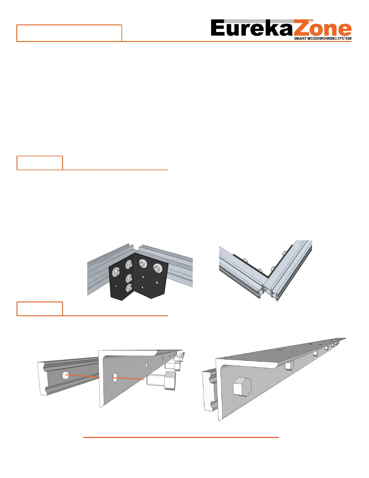
Step 1
Assembly of the bench frame begins with one corner, one end rail, and one side rail. Loosen the connectors
on the corner bracket. The face of the corner with the horizontal connector and the vertical connector
corresponds to the side of the bench frame. The face of the corner with only the horizontal connector
corresponds to the end of the bench frame. Insert the 22.5” SSME End Rail (Part B) onto the corner
connector(Part L). Then insert the 48” SSME Side Rail (Part A) onto the corner connector (Part L). The Side
Rail (Part A)overlaps the End Rail(Part B) by 3/4” as shown in the diagrams. Tighten all of the nuts with a 1/2”
nut driver or wrench.
Step 2
Attach the Support Connectors (Part E) to the Support Brackets (Part F) using the included hex screws(Part G).
Do not tighten the screws so the connector remains loose for the next step.
V15-01
Page 2
 Loading...