Do you have a question about the Eurotherm 3216i and is the answer not in the manual?
| Control | PID |
|---|---|
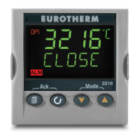
| Display | LED |
| Input Type | Thermocouple, RTD |
| Output Type | Relay |
| Communication | Modbus |
| Power Supply | 100-240 V AC |
| Operating Temperature | 0 to 50 °C |
Details items included in the instrument box for setup and initial inspection.
Illustrates the front panel dimensions of various indicator models: 32h8i, 3216i, and 3204i.
Shows side and top panel dimensions for different indicator models.
Provides general instructions and requirements for installing the indicator into a panel.
Step-by-step guide for mounting the indicator securely into a control panel.
Specifies the required panel cut-out dimensions for indicator installation.
Outlines minimum spacing requirements between multiple indicators for proper installation.
Instructions on how to safely remove the indicator from its protective sleeve.
Explains the structure and options for creating a hardware ordering code.
Illustrates the terminal connections for the 32h8i indicator model.
Shows the terminal connections for the 3216i indicator model.
Depicts the terminal connections for the 3204i indicator model.
Specifies recommended wire sizes for secure terminal connections.
Details wiring requirements for various sensor input types: thermocouple, RTD, mA/mV.
Explains standard relay and analogue output configurations.
Outlines power supply requirements and connection methods for the indicator.
Covers EIA232 and EIA485 communication setup and wiring.
Details input/output configurations specific to the 3216i model.
Details essential safety guidelines for personnel, enclosure, wiring, and power.
Specifies voltage limits and precautions for terminal connections.
Discusses measures for ensuring safe operation in environments with conductive pollution.
Explains considerations for fitting separate over-temperature protection units.
Guides the initial configuration of a new indicator using Quick Configuration.
Identifies and explains the function of front panel indicators and buttons.
Introduces parameters accessible for daily operation without a passcode.
Describes the procedure to access the secured Operator Level 2.
Lists and describes parameters available for adjustment in Level 2.
Explains methods for calibrating strain gauge transducers and indicators.
Details the procedure for calibrating a load cell directly.
Outlines calibration by comparing against a reference device.
Describes storing and recalling sets of parameter values for different processes.
Describes features specific to FM and Alarm unit configurations.
Describes shunt calibration for strain gauge transducer adjustment.
Step-by-step guide for manual calibration of transducer points.
Explains the process for automatic strain gauge calibration.
Describes access to all parameters for advanced configuration and adjustment.
Details access to fundamental instrument configuration settings.
Provides steps to switch between operator access levels.
Illustrates the navigation structure for accessing parameters within iTools.
Details parameters available under the ACCESS list header for security.
Lists parameters that configure the input to match specific sensors.
Details available input types and their corresponding operational ranges.
Explains how to apply a user-defined offset to the process variable reading.
Details scaling linear inputs to match displayed readings with transducer outputs.
Configuration details for Output Channel 1 on 32h8i and 3204i models.
Configuration for I/O Channel 1 on the 3216i model.
Configuration details for Output Channel 2 on the 3216i model.
Configuration for Output Channel 3 on specific models.
Details configuration for the AA Relay Channel (Output 4).
Lists parameters for configuring digital input functions.
Lists and describes the various types of alarms available: High, Low, Rate of Change.
Describes alarm behavior after power interruptions and latching states.
Details parameters for configuring individual alarms like type, threshold, and hysteresis.
Lists possible faults and recommended actions for troubleshooting.
Instructions on how to store current instrument settings into a recipe.
Steps for loading and activating a saved recipe.
Details the wiring requirements for EIA232 and EIA485 communication interfaces.
Lists parameters for configuring Modbus communication settings.
Step-by-step guide for configuring the Modbus instrument address.
Lists Modbus addresses for various instrument parameters.
Procedures for verifying the accuracy of input calibration.
Explains how to apply offsets to process values for known errors.
Explains the process for calibrating mV, thermocouple, and RTD inputs.
Procedures for calibrating analog output signals like mA and Voltage.
Lists parameters relevant to the calibration process.
How to load Instrument Definition Modules required for iTools.
Explains methods for connecting a PC to the instrument for configuration.
Guides on launching and navigating the iTools software interface.
How to use the iTools configuration wizard for setup.
Steps for configuring input parameters via the wizard.
How to set up alarms using the iTools wizard interface.
Steps to configure Output 1 settings within the wizard.
Process for customizing display messages using iTools.
Guide on defining and editing recipes through iTools.
Explains how to customize the indicator's display behavior.
How to configure settings via the iTools browser interface.
Steps to configure input parameters using the browser view.
How to customize alarm messages in iTools via browser.
How to adjust parameter access levels using the browser.
Instructions for loading custom linearisation tables.
How to set up and manage recipes using iTools.
Provides a summary of configured features and terminal wiring.
Describes copying configurations between instruments or to files.


