EasyManua.ls Logo

Eurotherm 32h8i User Manual

Eurotherm 32h8i
88 pages
To Next Page IconTo Next Page
Page #1 background imageLoading...
Page #1 background image
3216i, 32h8i, 3204i
User
Manual
3200i Range Process Indicators and Alarm Units
HA029006/5
Sept 2012

Table of Contents

Other manuals for Eurotherm 32h8i

Question and Answer IconNeed help?

Do you have a question about the Eurotherm 32h8i and is the answer not in the manual?

Eurotherm 32h8i Specifications

General IconGeneral
BrandEurotherm
Model32h8i
CategorySecurity System
LanguageEnglish

Summary

1. Installation and Basic Operation

1.1 Unpacking Your Indicator

Details the items included in the indicator packaging for setup.

1.2 Dimensions Front Views

Shows front view dimensions for different models.

1.3 Dimensions - Side and Top Views

Illustrates side and top dimensions for various models.

1.4 Step 1: Installation

1.4.1 Panel Mounting the Indicator

Describes the process of mounting the indicator onto a panel.

1.4.2 Panel Cut-out Sizes

Provides panel cut-out dimensions for different indicator models.

1.4.3 Recommended Minimum Spacing of Indicators

Specifies minimum spacing requirements between indicators.

1.4.4 To Remove the Indicator from its Sleeve

Explains how to safely remove and reinsert the indicator from its sleeve.

1.5 Ordering Code (Hardware)

2. Step 2: Wiring

2.1 Terminal Layout 32h8i Indicator

Details terminal connections for the 32h8i indicator model.

2. Step 2: Wiring

2.2 Terminal Layout 3216i Indicator

Details terminal connections for the 3216i indicator model.

2.3 Terminal Layout 3204i Indicators

Details terminal connections for the 3204i indicator models.

2. Step 2: Wiring

2.4 Wire Sizes

Specifies acceptable wire sizes for terminal connections.

2.5 Sensor Input (Measuring Input)

Provides guidance on connecting various sensor inputs.

2.6 Outputs - 1/8 and 1/4 DIN Indicators

Details configuration of relay and retransmission outputs.

2. Step 2: Wiring

2.6.4 Digital Inputs A and B

Explains the function and availability of digital inputs.

2.6.5 Transducer Supply

Details the 10Vdc transducer supply for specific models.

2.7 Indicator Power Supply

Covers power supply requirements and external fusing.

2.8 Example Wiring Diagram

Illustrates a typical wiring setup for a strain gauge connection.

2. Step 2: Wiring

2.9 Digital Communications (Optional)

Explains Modbus communication options (EIA232/EIA485).

2.10 Additional Connections for 3216i

Details specific input/output configurations for the 3216i model.

3. Safety and EMC Information

3.1 Installation Safety Requirements

Covers safety symbols, personnel, enclosure, wiring, and power isolation.

3. Safety and EMC Information

Installation and Safety Precautions

Covers voltage limits, pollution, grounding, over-temperature, EMC, and wire routing.

4. Switch On

4.1 New Indicator

Guides through initial configuration using Quick Codes.

4.2 Pre-Configured Indicator or Subsequent Starts

Describes the startup sequence for pre-configured units.

4.3 Front panel layout

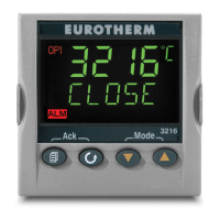
Explains the indicator's front panel components and their functions.

4. Switch On

4.3.1 Alarm Indication

Describes how alarms are indicated via display and beacon.

4.3.2 Out of Range Indication

Explains how the display indicates out-of-range input values.

4.3.3 Sensor Break Indication

Details how sensor break conditions are indicated.

4.4 Operator Parameters in Level 1

Introduces parameters accessible for daily operation.

4. Switch On

4.4.1 Tare Correction

Explains how to use the tare function for weighing applications.

5. Operator Level 2

5.1 To Enter Level 2

Guides on accessing Operator Level 2 using a passcode.

5. Operator Level 2

5.2 Level 2 Parameters

Lists and describes parameters available in Level 2.

5. Operator Level 2

5.2 Level 2 Parameters (Continued)

Continues listing and describing Level 2 parameters.

5.3 Strain Gauge Calibration

5.3 Strain Gauge Calibration

5.3.1 Load Cell Calibration

Details the procedure for calibrating a load cell directly.

5.3.2 Comparison Calibration

Explains calibrating against a second reference device.

5.3 Strain Gauge Calibration

5.3.3 Shunt Calibration

Describes shunt calibration for strain gauge transducers.

5.3.4 Manual Calibration

Outlines the manual calibration steps for zero and span.

5.3.5 Automatic Calibration

Details the process for automatic strain gauge calibration.

5.3.6 Calibration Using a Digital Input

Explains calibration via an external digital input.

5.4 Recipes

5.4.1 To Store Values in a Recipe

Guides on saving current settings into one of five recipes.

5.4.2 To Load a Recipe

Explains how to recall stored recipe settings.

5.5 FM and Alarm Units

Details specific features for FM and Alarm units.

6. Access to Further Parameters

6.1 Level 3

Describes Level 3 access for all operating and alterable parameters.

6.2 Configuration Level

Explains Configuration Level for fundamental instrument changes.

6. Access to Further Parameters

6.2.1 To Select Access Level 3 or Configuration Level

Provides step-by-step instructions for selecting Level 3 or Configuration.

6.3 Parameter lists

6.3.1 To Choose Parameter List Headers

Explains how to navigate and select parameter list headers.

6.3.2 To Locate a Parameter

Guides on selecting specific parameters within a list.

6.3 Parameter lists

6.3.3 How Parameters are Displayed

Details the format of parameter display and scrolling banner.

6.3.4 To Change a Parameter Value

Explains how to modify parameter values using the keys.

6.3.5 To Return to the HOME Display

Describes how to return to the main display from parameter lists.

6.3.6 Time Out

Explains the timeout behavior for certain parameters.

6.4 Navigation Diagram

6.5 Access Parameters

7. Process Input

7.1 Process Input Parameters

Lists and describes parameters for configuring process inputs.

7. Process Input

7.1 Process Input Parameters (Continued)

Continues listing input parameters like Type, Units, and Filter.

7.1.1 Input Types and Ranges

Details available input types and their corresponding ranges.

7. Process Input

7.1.1 Input Types and Ranges (Continued)

Continues listing input types and their ranges.

7.1.2 Units

7.1.3 PV Offset

7.1.4 PV Input Scaling

8. Input/Output Channels

8.1 Output Channel 1 (OP-1) - 32h8i and 3204i Indicators

Details configuration of Output 1 for specific models.

8.2 Input/Output Channel 1 (I/O-1) - 3216i Indicator

8.3 Output Channel 2 (OP-2) - 3216i Indicator

8.3.1 Sense

8.3.2 Source

8.3.3 Power Fail

8.3.4 Example: To Configure OP-1 Relay to Operate on Alarms 1 and 2

8.4 Output Channel 3 (OP-3) - 32h8i, 32h8i/SG and 3204i Indicators

8.4.1 Output Scaling

Explains how to scale the DC output for desired readings.

8.5 AA Relay Channel (AA) (Output 4)

9. Digital Input

9.1 Digital Input Parameters

Lists and describes parameters for digital input configuration.

10. Alarms

10.1 Types of Alarm

Lists and describes the six available alarm types.

10. Alarms

10.1.1 Alarm Relay Output

Details how alarms operate relay outputs.

10.1.2 Alarm Indication

Explains how alarms are visually indicated on the display and beacon.

10.1.3 To Acknowledge An Alarm

Guides on acknowledging active alarms.

10.1.4 Pre-Alarms

Describes how pre-alarms are activated relative to alarm setpoints.

10.2 Behaviour of Alarms After a Power Cycle

10.2.1 Example 1

Illustrates alarm behavior with non-latching configuration.

10.2.2 Example 2

Illustrates alarm behavior with manual latching.

10.2.3 Example 3

Illustrates alarm behavior with auto latching.

10.3 Alarm Parameters

10.3.1 Example: To Configure Alarm 1

10.4 Diagnostic Alarms

11. Recipe

11.1 To Save Values in a Recipe

Guides on saving current settings into one of five recipes.

11. Recipe

11.2 To Save Values in a Second Recipe

Demonstrates saving modified settings into a recipe.

11.3 To Select a Recipe to Run

Explains how to recall stored recipe settings.

12. Digital Communications

12.1 Digital Communications Wiring

Details wiring for EIA232 and EIA485 communication interfaces.

12.2 Digital Communications Parameters

12.2 Digital Communications Parameters

12.2.1 Broadcast Communications

Explains simple master communication for sending single values.

12.2.2 Broadcast Master Communications

Details master configuration for sending values to slaves.

12.2.3 Wiring Connections

Shows wiring diagrams for EIA232 and EIA485 master/slave connections.

12.3 Example: To Set Up Instrument Address

12.4 DATA ENCODING

12.5 Parameter Modbus Addresses

13. Calibration

13.1 To Check Input Calibration

Explains how to verify input calibration accuracy.

13.1.1 Precautions

Lists important precautions before calibration.

13. Calibration

13.1.2 To Check mV Input Calibration

Details checking mV input calibration with a source.

13.1.3 To Check Thermocouple Input Calibration

Explains checking thermocouple calibration and CJC.

13.1 To Check Input Calibration

13.1.4 To Check RTD Input Calibration

Guides on checking RTD calibration using a decade box.

13.2 Offsets

13.2.1 Five Point Offset

Details the procedure for a five-point offset calibration.

13.3 Input Calibration

13.3 Input Calibration

13.3.1 To Calibrate mV Range

Details calibrating the mV range, including mA inputs.

13.3.2 To Calibrate Thermocouple Ranges

Explains calibrating thermocouple ranges and CJC.

13.3.3 To Calibrate RTD Ranges

13.4 Output Calibration

13.4.1 To Calibrate mA Outputs

Details calibrating mA outputs using an ammeter.

13.4.2 To Return to Factory Calibration

Explains how to restore factory calibration settings.

13.4.3 Transducer Calibration

Refers to section 5.3 for transducer calibration procedures.

13.5 Calibration Parameters

14. Configuration Using iTools

14.1 Loading an IDM

Explains how to load Instrument Definition Modules (IDMs).

14.2 Connecting a PC to the Indicator

Details methods for connecting a PC to the indicator.

14.3 Starting iTools

14.4 Configuring the Indicator Using the Wizard

14.4.1 To configure the Input

Details configuring the input type, units, and range via the wizard.

14.4 Configuring the Indicator Using the Wizard

14.4.2 To Configure Alarms

Guides on setting alarm types, thresholds, and hysteresis.

14.4.3 To Configure Output 1

Explains how to configure output relay behavior based on alarms.

14.4.4 To Customise Messages

14.4.5 To Promote Parameters

14.4.6 To Set Up Recipes

14.4.6.1 Recipe Definition

Guides on defining which parameters are included in a recipe.

14.4.6.2 Editing Recipe

Explains how to set values for parameters within a recipe.

14.4.6.3 Recipe Names

Describes how to assign names to stored recipes.

14.4.7 To Customise the Display

14.4.8 Summary Tab

14.5 Configuring the Indicator Using the Browser Views

14.5.1 To configure the Input

Guides on configuring input parameters via the browser view.

14.5.2 To Configure Alarms

Details configuring alarms using the browser view.

14.5.3 To Customise Messages

14.5.4 To Promote Parameters

14.6 To Load A Special Linearisation Table

14.7 To Set up Recipes

14.7.1 Example: Set Two Different Alarm Thresholds and Store in Recipes 1 and 2

Demonstrates setting and storing alarm thresholds in recipes.

14.8 Summary

14.9 Cloning

14.9.1 Save to File

Guides on saving instrument configuration to a clone file.

14.9.2 To Clone a New Indicator

Explains transferring configuration to a new instrument.

15. TECHNICAL SPECIFICATION

16. Parameter Index

17. Index

Related product manuals