INSTALLATION INSTRUCTIONS
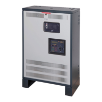
OUTSIDE THE LUMINAIRE
MIP-36
LED test switch
1. SPECIFICATION OF MIP-36
2. INSTALLING THE MIP-36
The MIP-36 can be mounted inside or outside (nearby or on top of*) the luminaire.
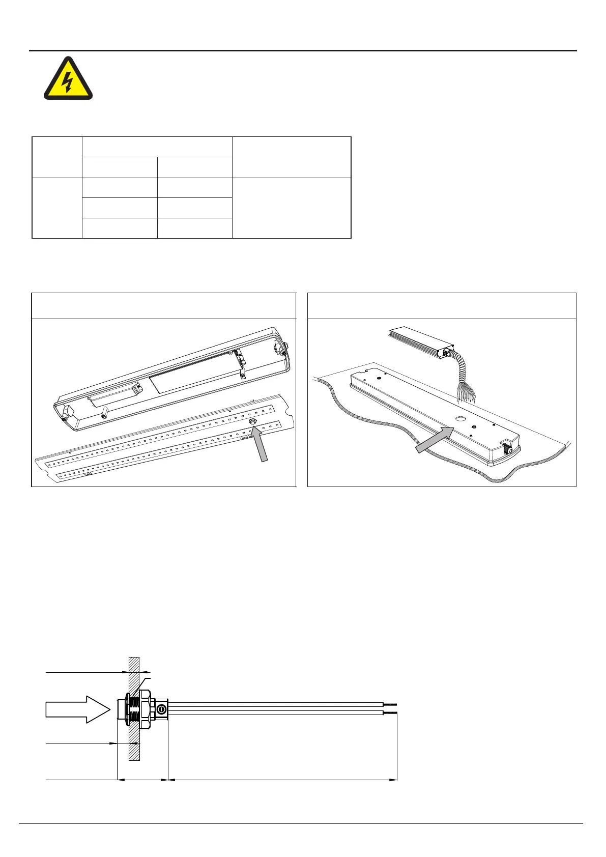
3. INSTALLING THE LED TEST SWITCH (LTS)
Select a convenient location for the LTS so that it can be seen after installation.
Drill a 1/2"(12 mm) hole for mounting the LTS.
Connect the wires from LTS to the MIP-36 model according to the wiring diagram on page 3.
MIP-36
One 7/8" (22mm) hole for
conduit connector for MIP-36
MIP-36
Output
Output Power
Voltage
Model
Input
230V/50Hz
120V/60Hz
277V/60Hz
230V/50Hz
120V/60Hz
277V/60Hz
Max. 36W
With dimmable or
non-dimmable load
INSIDE THE LUMINAI
RE
EVENLITE WWW.EVENLITE.COM
REV-1
Z410205 2
All dimensions are typical
Dimension unit: mm [inch]
Tolerance: ±1 [0.04]
Mounting Hole:
ø12.0 [ø0.47]
25.0 [0.98]
240 [9.45]
PUSH TO TEST
T=5 [0.20]
6.0 [0.24]
*NOTICE:
The MIP-36 Emergency Inverter Pack are rated for operation with an internal pack ambient between 0°C to
50°C. To meet this rating, warranty condition and ensure optimum component life, it is recommended that
the pack be mounted remotely from the light fixture or high ambient temperatures. Where it is necessary
to mount directly to the light fixture, the installer should verify that the stabilized fixture surface
temperature rise does not contribute radiant heat directly to the pack surface; resulting in the pack
internal ambient temperature exceeding the max. 50°C rating. Locate or space the pack as necessary.
CAUTION: MAKE CERTAIN THE AC POWER IS OFF AND THE MIP-36 BROWN WIRE UNIT
CONNECTOR IS DISCONNECTED UNTIL THE INSTALLATION IS COMPLETE.
 Loading...