6
Installation (continued)
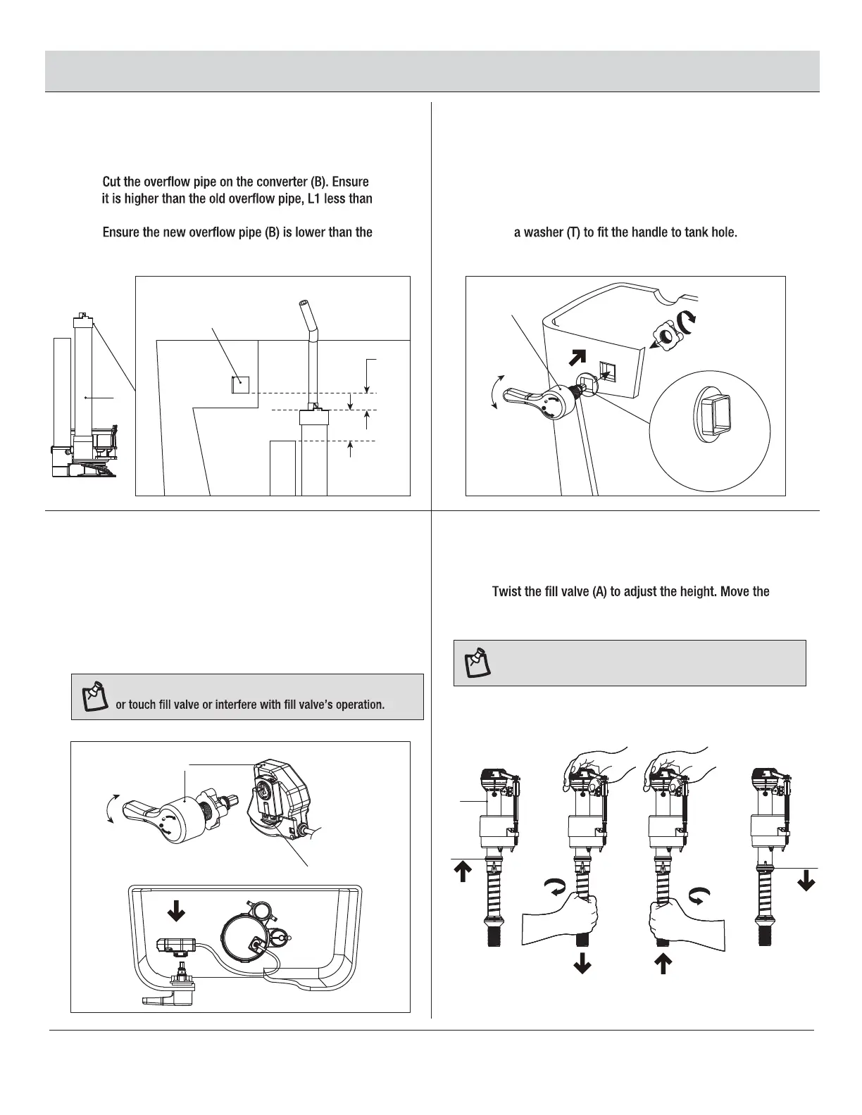
CUT NEW OVERFLOW PIPE POSITION THE HANDLE
9 10
11 12
□ Position and hand tighten the handle of the trip
lever assembly (C) in the tank hole.
□ When the tank hole diameter is greater than 17.5 mm,
use
□
1 in.
□
tank hole, L2 greater than 1 in.
ATTACH CONTROL BOX
ADJUST HEIGHT OF NEW
FILL VALVE
□ Push in the black release of the trip lever assembly (C).
□ Attach the control box of the trip lever assembly (C)
to the handle until you hear a click. This ensure the
clip has secured the control box to the handle.
□
lock ring up. After setting the height, move the lock
ring down.
NOTE: Control box and control cable MUST NOT kink
NOTE: Increase height – twist lower shank clockwise
Decrease height – twist lower shank counter clockwise.
A
L1
O.L
Tank hole
L2
B
Full
Half
Release-push
C
C
Full
Half
Optional
Washer(T)
Lock
Ring
Lock
Ring