13
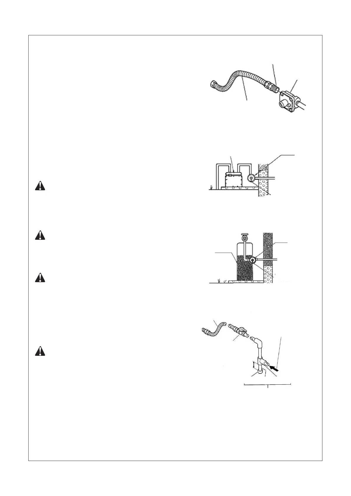
Figure 11 - Attaching Flexible Gas
Hose to Heater Gas Regulator
Figure 12-A - External Regulator
with Vent Pointing Down For NG
Figure 12-B - External Regulator
with Vent Pointing Down For LP
A CSA/AGA design-certied equipment shutoff valve with
1/8-inch NPT tap is an acceptable alternative to test gauge connec-
tion. Purchase the optional CSA/AGA design-certied equipment
shutoff valve from your dealer.
The installer must supply an external regulator. The external regula-
tor will reduce incoming gas pressure. You must reduce incoming gas
pressure to minimum allowable on rating label. If you do not reduce
incoming gas pressure, heater regulator damage could occur. Install
external regulator with the vent down as shown in Figure 12. Pointing
the vent down protects it from freezing rain or sleet.
Installation must include equipment shutoff valve, union, and plugged
1/8-inch NPT tap. Locate NPT tap within reach for test gauge hook
up. NPT tap must be upstream from heater (see Figure 13). To pre-
vent performance problems, Propane/LP tank of less than 100 lbs.
capacity is not recommended.
IMPORTANT: Install an equipment shutoff valve in an accessible
location. The equipment shutoff valve is for turning on or shut-
ting off the gas to the appliance. Apply pipe joint sealant lightly
to male threads. This will prevent excess sealant from going
into pipe. Excess sealant in pipe could result in clogged heater
valves.
CAUTION: Use only a new, black iron or steel pipe. Internally-
tinned copper tubing may be used in certain areas. Check your
local codes. Use pipe of 1/2 inch diameter to allow proper gas
volume to heater. If pipe is too small, undue loss of pressure will
occur.
CAUTION: Use pipe joint sealant that is resistant to natural
gas(NG) or liquid petroleum (LP) gas.
We recommend that you install a sediment trap in the supply line as
shown in Figure 13. Place sediment trap where it is within reach for
cleaning and where trapped matter is not likely to freeze. A sediment
trap traps moisture and contaminants. This keeps them from going
into heater controls. If sediment trap is not installed or is installed
incorrectly, heater may not run properly.
IMPORTANT: Hold pressure regulator with wrench when con-
necting it to gas piping and/or ttings.
Figure 13 - Gas Connection
Flexible Gas Hose
(if allowed by local codes)
Fitting
Heater Gas
Regulator
Gas meter
External
Regulator
Vent Pointing
Down
External
Regulator
Propane/LP
Supply Tank
Vent Pointing
Down
Approved Fiexible Gas Hose
(if allowed by local codes)
LP: From External Regulator
(11” W.C. to 14” W.C. Pressure)
NG: From Gas Meter (5” W.C.
to 10.5” W.C. Pressure)
CSA Design Certied
Epuipment Shutoff Valve
With 1/8 NPT Tap
3” Minimum
Cap Pipe Nipple Tee Joint
Sediment Trap
 Loading...