12
CONNECTING TO GAS SUPPLY
WARNING: A qualied service technician must connect heater to gas supply. Follow all local codes.
WARNING: This appliance requires 1/2-inch NPT (National Pipe Thread) inlet connection to the pressure regulator.
WARNING: Never connect heater to private (non-utility) gas wells. This is commonly known as well head gas.
CAUTION: Never connect heater directly to the natural or propane/LP supply. This heater requires an external regu-
lator (not supplied). Install the external regulator between the heater and natural or propane/LP supply.
1. Apply pipe joint sealant lightly to tting threads. Connect approved exible gas hose to gas regulator of heater (see
Figure 11 on page 13). NOTE: Never apply pipe sealant to are tting threads
IMPORTANT: Hold gas regulator with wrench when connecting exible gas hose.
2. Locate masonry screws in hardware package.
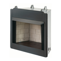
3. Position heater base assembly in replace.
4. Place logs in their proper position on heater base.
5. Center heater base and logs front-to-front and side-to-side in replace.
INSTALLING HEATER BASE ASSEMBLY
CAUTION: Do not remove the metal data plates attached to the heater base assembly. The data plates contain
important warranty Information.
WARNING: You must secure this heater to replace oor. If not, heater will move when you adjust controls. Mov-
ing heater may cause a gas leak.
WARNING: If installing in a sunken replace, special care is needed. You must raise the replace oor to allow
access to heater control panel. This will insure adequate air ow and guard against sooting. Raise replace oor
with noncombustible material.
CAUTION: Do not pick up heater base assembly by the burner. This could damage heater. Only handle base
assembly by grates.
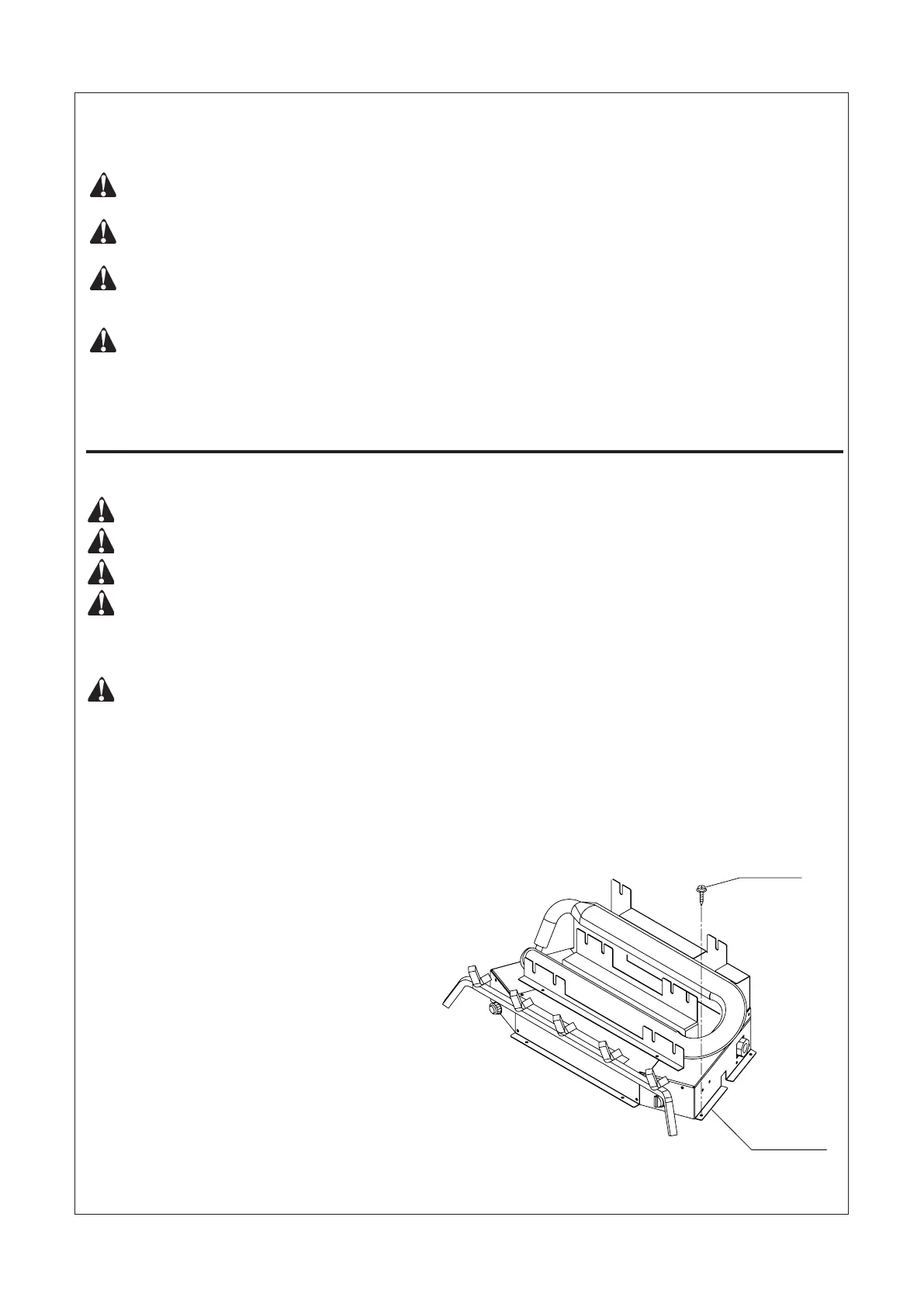
Figure 10 - Attaching Heater Base to Fireplace Floor
INSTALLATION
6. Carefully remove logs without moving heater base.
7. Mark screw locations through holes in mounting brackets
(see Figure 10). If installing in a brick-bottom replace,
mark screw locations in mortar joint of bricks.
8. Remove heater base from replace.
9. Drill holes at marked locations using 3/16-inch drill bit.
10. Attach base assembly to replace oor using two
masonry screws (in hardware package) (see Figure 10).
Masonry Screw
Mounting Bracket