Thank you for purchasing an EVGA product.
Please remember to register your product at:
www.evga.com/register
For the latest drivers and updates for your
product please visit:
www.evga.com/support/drivers
To visit and search our knowledge base and
product FAQ please visit:
www.evga.com/FAQ
To visit the EVGA community message
boards please visit:
forums.evga.com
For more information about these services
as well as our terms and conditions please visit
www.evga.com
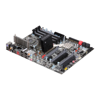
24 Pin ATX Power
IDE Channel
Post LED
Fan Header
Fan Header
SATA Ports
GND GND GND
RX
+
TX
-
TX
+
RX
-
SATA Port
PC Speaker
Serial
CMOS
Reset
Button
Power
Button
Fan
Header
8 Pin 12v Power
CPU Fan Header
SupportPremium Services
dvanced RMA
Stepping-Up Your Customer Service
EVGA Corp. 2900 Saturn Street, Suite B Brea, CA 92821
Connector
USB 2.0 Header Connector
SignalPin
1
1
2
3
4
5
6
7
8
9
10
3
5
7
9
5V_DUAL
D
-
D
+
GND
Empty
5V_DUAL
D
-
D
+
GND
No Connect
2
4
6
8
10
SignalPin
Connector
Front Audio Connector
SignalPin
1
2
3
4
5
6
7
8
9
10
PORT1_L
AUD_GND
PORT1_R
PRECENCE J
PORT2_R
SENSE1_RETURN
SENSE_SEND
Empty
PORT2_L
SENSE2_RETURN
10
9
8
7
6
5
4
3
2
1
Connector
IEEE 1394a Connector
1
2
3
4
5
6
7
8
9
10
SignalPin
1
2
3
4
5
6
7
8
9
10
TPA
+
TPA
-
GND
GND
TPB
+
TPB
-
+
12V
+
12V
Empty
GND
Connector
SPDIF
DefinitionPin
1
2
3
4
5
6
Power
No Pin
SPDIF
SPDIFI
GROUND
GROUND
2 4
1 3
6
5
Please see the manual for more details.
ATTENTION:
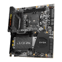
EVGA recommends applying 1.65V or less when
setting the DIMM Voltage. This will support long
term stability.
PWRLED PWRSW Blank
HD_LED RESET No
Connect
2
+ -
+ -
1
10
9
Limited Lifetime Warranty
upon product registration
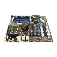
1. PS/2 Keyboard Port
2. USB 2.0 Ports
3. Clear CMOS
4. Coaxial SPDIF Output
5. Optical SPDIF Output
6. IEEE1394a (Firewire) Port
7. e-SATA Port
8. LAN Ports (10/100/1000)
9. Audio Ports
5
5
3
3
1
1
6
6
42
2 4
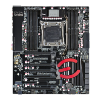
One DIMM: If using 1 DIMM (Single Channel),
install into: DIMM slot 1.
Two or Four DIMMs: If using 2 DIMMs (Dual Channel),
install into: DIMM slots 1 and 3. If using 4 DIMMs
(Dual Channel), install into: DIMM slots 2, 1, 4, and 3.
Three DIMMs: If using 3 DIMMs (Triple Channel),
install into: DIMM slots 1, 3, and 5.
Six DIMMs: If using more than 4 DIMMs, use:
DIMM slots 2, 1, 4, and 3 then proceed to occupy
the following DIMM slots in this order: 5 and 6.
Ground
12V
Sense
Ground
12V
Sense
Control
Ground
12V
Sense
Ground
12V
Sense
Ground
12V
Sense
2 3 5 2 7
9
1 4 6 8
2
Color info : CMYK Please match colors to:
PMS © Orange 021 PMS © 485 c PMS © Yellow c PMS © Hexachrome Green PMS © Process Cyan K 100% K 85%