8
The below table contains the nal nished opening sizes once
the product has been installed.
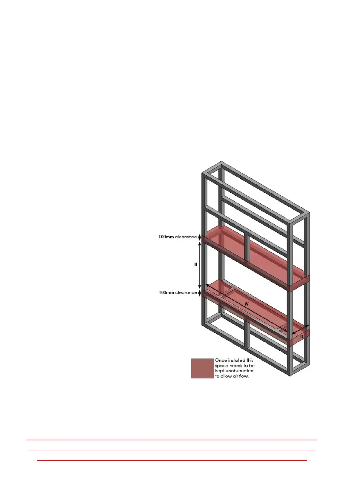
Please see Figure 1: as a example of a installaon.
Please refer to technical specicaon table for further
informaon, with reference aperture measurements.
Please note: This table is only an example of an installaon and is only applicable to GF models
Model Width Depth Height
e500 492mm 310mm 609mm
E600 637mm 190mm 638mm
e630 639mm 310mm 640mm
e640 460mm 190mm 843mm
e700 641mm 190mm 480mm
e730 642mm 310mm 477mm
e710 710mm 190mm 790mm
e800 805mm 310mm 790mm
e810 808mm 310mm 1208mm
e900 836mm 190mm 695mm
e1000 1002mm 190mm 475mm
e1030 1004mm 310mm 555mm
e1250 1254mm 310mm 556mm
e1500 1506mm 310mm 555mm
e1560 1508mm 310mm 808mm
e1800 1754mm 310mm 611mm
e2400 2402mm 310mm 631mm
Model W D H
e500 492mm N/A 400mm
e600 637mm N/A 455mm
e630 639mm N/A 457mm
e640 460mm N/A 655mm
e700 641mm N/A 285mm
e710 710mm N/A 607mm
e730 642mm N/A 282mm
e800 805mm N/A 590mm
e810 808mm N/A 1003mm
e900 836mm N/A 492mm
e1000 1002mm N/A 275mm
e1030 1004mm N/A 355mm
e1250 1254mm N/A 357mm
e1500 1506mm N/A 355mm
e1560 1508mm N/A 605mm
e1800 1754mm N/A 410mm
e2400 2402mm N/A 430mm
The table to the le contains the minimum opening sizes
required to house a GF model. Please follow the D & H
measurement above and ensure that the W is no greater
than the chimney breast or opening that the product is to
be installed into. 10mm has been added to the depth of
the cut out to allow ample room for the re. Please
ensure once the re has been ed in place to allow the
recommended 100mm air gap above and below. This
measurement is internal and does not have to be
included into the cut out size (shown below).
Please note: We strongly recommend that when the frame work is being plastered and nished, you
leave an access hole for the power lead. This is to allow easy access for engineers/electricians in the
event of any maintenance being required, or in case the lead is unplugged during installaon.
Figure 1: