Do you have a question about the EWC Controls BMPlus 3000 and is the answer not in the manual?
Lists the items included in the BMPlus 3000 package for setup and installation.
Details the function of the thermal circuit breaker for system protection against overloads.
Explains how the system manages indoor fan operation for heating, cooling, and purging.
Describes seven delay timers (Startup, Short Cycle, Changeover, Opposing Call, Staging, Supply Air, Purge) for safe operation.
Sets supply air temperature limits for cooling and heating cycle control.
Covers the reset button's functions and the emergency heat switch operation.
Configures the HVAC system type: Heat Pump, Gas/Oil Furnace, or Electric.
Selects Heat Pump mode: Restricted or Unrestricted during auxiliary heat.
Sets thermostat compatibility: Heat/Cool or Heat Pump thermostats.
Specifies the reversing valve signal for Heat Pump operation (O or B).
Chooses between Outside Air Temperature or Timer for auxiliary heat delay.
Enables/disables inhibiting auxiliary heat based on zone demand percentage.
Enables or disables the use of the included Supply Air Sensor.
Configures fan operation for Gas/Oil furnaces or Hydronic systems.
Details the necessary 24VAC transformer and power supply for the BMPlus 3000.
Illustrates wiring for various thermostat types: Heat Pump, Heat/Cool, and Wireless.
Provides wiring diagrams for connecting thermostats to radiant floor heating systems.
Shows wiring for single transformer Gas/Electric Furnace and A/C systems.
Details wiring for 2-Heat/1-Cool Heat Pumps with O-type reversing valves.
Illustrates wiring for Oil/Hydronic systems with separate transformers.
Explains wiring for Dual Fuel Heat Pumps with 3-Heat/2-Cool configurations.
Shows wiring for 2-stage Gas Heat and 2-stage AC systems.
Details wiring for 3-Heat/2-Cool Heat Pumps with B-type reversing valves.
Explains factory power wiring between expansion modules for simplified setup.
Highlights BMPlus 3000 compatibility with Dual Fuel Heat Pumps and staging options.
Describes the firmware feature that ignores demands from faulty zones.
Defines the function of each terminal on the zone module damper motor block.
Provides wiring diagrams for ESR, ND, URD, SID, and RSD damper models.
Charts recommend transformer sizes for BMPlus models based on damper type and quantity.
Outlines steps to test various damper motor types for proper operation.
The STATUS LED pulses to indicate proper microprocessor system status.
Indicates outdoor temperature status or sensor circuit issues.
Indicates supply air temperature status or sensor circuit issues.
Illuminate to show damper status and zone activity.
Indicate fan operation and heating/cooling stage activation (Y1, Y2, W1/B, W2/E).
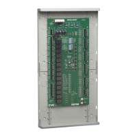
Details the BMPlus 3000 main module components and connections.
Guides on setting DIP switches and connecting expansion modules.
Explains the 2-position DIP switch settings for XM2 expansion modules.
Details DIP switch configurations for BMPlus 7000 XM2 expansion panels.
Illustrates wiring for Dual Fuel Heat Pumps with outdoor air or thermostat emergency input.
Shows wiring for 2-stage Gas Heat and 2-stage A/C systems with timer activation.
Provides solutions for HVAC system malfunctions based on LED status.
Guides on identifying and resolving 24VAC short circuits affecting the system.
Offers advice on testing thermostat connections and configurations.
| Brand | EWC Controls |
|---|---|
| Model | BMPlus 3000 |
| Category | Controller |
| Language | English |