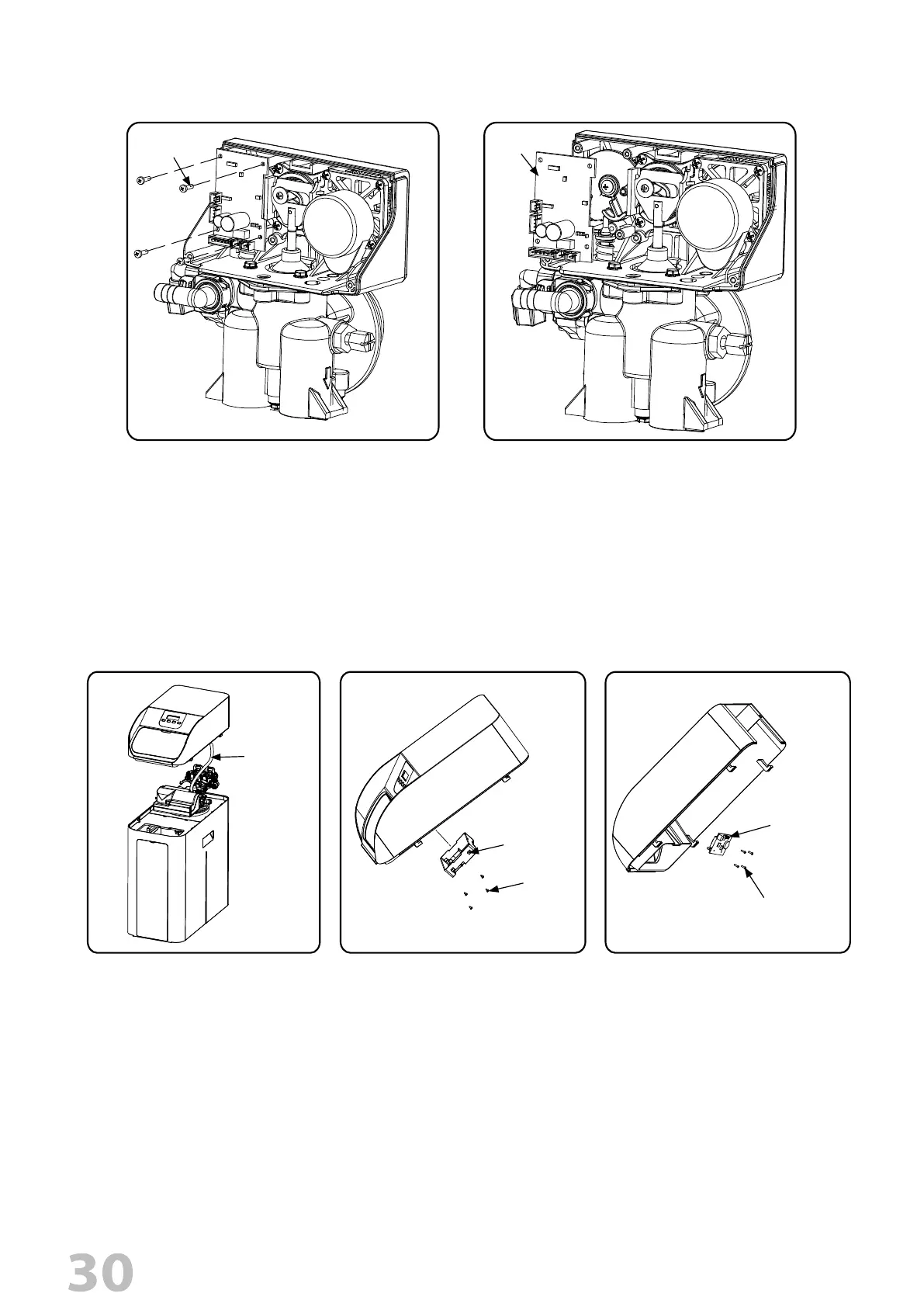
REPLACE DISPLAY
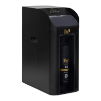
REPLACE CIRCUIT BOARD
1. Follow steps 1 to 3 of timer /Powerhead replacement.
2. Remove all the connections on PCB.
3. Remove the four screws from the PCB.
4. Replace the PCB.
4 X Screws
PCB
3. Remove the four screws attached
on display back cover.
4. Remove the display back cover.
5. Remove the four screws attached
on display PCB.
6. Remove the display PCB.
1.
Unplug electrical cord from outlet.
2. Remove the cover assy and disconnect
the wire connection.
Communication
wire conncetions
4 X Screws
1 X Display Back
Cover
4 X Screws
1 X Display PCB