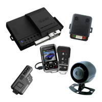
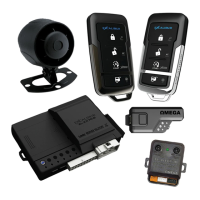
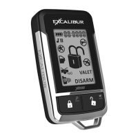
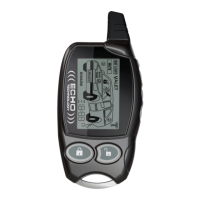
Do you have a question about the Excalibur AL-XX50-EDPB and is the answer not in the manual?
Details the connections for the 6-pin main wire harness.
Instructions for connecting the constant +12v power supply.
Guidance for the primary ignition switch input/output connection.
Connection for system ground input.
Connects starter interrupt and anti-grind functionality.
Critical safety circuit for brake pedal input.
Critical safety circuit for neutral safety input.
Input for engine RPM signal for detection.
Output for flashing parking lights.
Safety circuit for hood trigger input.
Input for door trigger to detect entry.
Output for trunk release or auxiliary function.
Input for the light relay N/O connection.
Output for the light relay COM connection.
Input for the horn relay N/O connection.
Output for a third channel activation.
Input to activate the system's remote start function.
Input to arm the vehicle's alarm system.
Input to disarm the vehicle's alarm system.
Negative output for the starter circuit.
Positive output for driving relay coils.
Negative output for the ignition circuit.
Negative output for locking vehicle doors.
Primary negative output for unlocking vehicle doors.
Secondary negative output for unlocking vehicle doors.
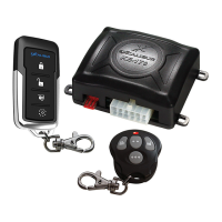
Port for installing BLADE cartridges for module functionality.
Harness connection for BLADE modules.
Ports for connecting dual zone sensors.
Installation of the window mount antenna module.
Overview of the system's status indicator lights.
Procedure to program the tach wire for engine detection.
Method for programming additional or replacement transmitters.
Procedure to enable the Unauthorized Transmitter Alert feature.
| Operating Voltage | 12V DC |
|---|---|
| Remote Start Range | Up to 3000 feet |
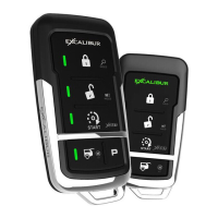
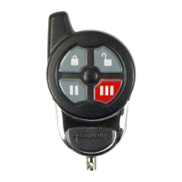
| Number of Buttons on Remote | 5 |
| Keyless Entry | Yes |
| Engine Start | Yes |
| Engine Stop | Yes |
| Lock/Unlock | Yes |
| Trunk Release | Yes |
| Installation | Professional installation recommended |
| Alarm Features | Shock sensor |
| Security Features | Starter kill |
| Compatibility | Most vehicles with automatic transmission |
| Security System | Yes |
| Battery Life | 1 year (typical usage) |
| Remote Confirmation | Audible and visual confirmation via LED on remote |
