RED BLACK
Chassis Ground
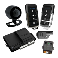
High Output 6-Tone Mini Siren
(P/N: AU-73M - Optional)
AL-XX70-B Wire Diagram
Push-Button
Status Light
(P/N: AU-LED-PB2)
Status Light
Valet / Programming
Button
A
WHITE 6 PIN HIGH CURRENT POWER HARNESS (P/N: H-RS6E*)
PIN POL. COLOR FUNCTION DATA**
1 (+) PINK/WHITE IGNITION / Accessory / Start - INPUT/OUTPUT***
4
2 (+) VIOLET START - INPUT/OUTPUT
4
3 (+) ORANGE ACCESSORY / Ignition / Start - INPUT/OUTPUT***
4
4 (+) RED/WHITE Feed For ORANGE (A3) / VIOLET (A2) / WHITE (B7) - INPUT (30A Fused)
5 (+) RED System Power - INPUT (30A - Fused)
6 (+) PINK
IGNITION / Accessory / Start - INPUT/OUTPUT***
4
4
36
1
F
WHITE 4 PIN PLUG-IN SENSOR PORTS (harness included w/ optional sensors)
G
TEMPERATURE SENSOR - DO NOT COVER
(For high/low temp auto start and for automatic low temp crank extender)
H
BLADE CARTRIDGE PORT - For OL-BLADE-AL64 or OL-BLADE-TB
B
WHITE 18 PIN MAIN INPUT/OUTPUT HARNESS (P/N: H-RS18A)
PIN POL. COLOR FUNCTION DATA**
1 (-) VIOLET/WHITE Tach Pulse Input (coil or injector) - INPUT
4
2 (+/-) BLACK/RED Light Flash (Prog. - Installer Feature #5) Relay Pin 87 - INPUT
4
3 (+/-) GREEN/VIOLET Light Flash (Prog. - Installer Feature #5) Relay Pin 30 - OUTPUT (10A)
4
4 (-) WHITE/BLACK Light Flash - OUTPUT (250ma)
4
5 (+) BROWN/RED Brake Pedal RS Shutdown - INPUT
4
6 (+/-) WHITE/RED Light Flash (Prog. - Installer Feature #5) Relay Pin 87a - INPUT
4
7 (+) WHITE Light Flash - OUTPUT (10A Fused)
4
8 (+/-) BROWN/BLACK Horn Honk (Prog. - Installer Feature #19) Relay Pin 87a - INPUT
9 (+/-) VIOLET/BLACK Horn Honk (Prog. - Installer Feature #19) Relay Pin 87 - INPUT
10 (-) GREEN Door Trigger - INPUT
4
11 (+) VIOLET Door Trigger - INPUT
4
12 (-) RED/WHITE Trunk Release - OUTPUT (250ma)
4
13 (-) ORANGE Starter Kill - OUTPUT (500ma)
14 (-) BLACK System Ground - INPUT
15 (-) BLACK/WHITE Parking Brake/Neutral Safety - INPUT (Required For Manual Transmission)
4
16 (-) GRAY Hood Trigger - INPUT
4
17 (+) BROWN Siren - OUTPUT (1A)
18 (+/-) BLUE/BLACK Horn Honk (Prog. - Installer Feature #19) Relay Pin 30 - OUTPUT (10A)
110
918
C
RED 4 PIN DOOR LOCK/UNLOCK HARNESS (P/N: DLP-N4)
PIN POL. COLOR FUNCTION DATA**
1 (-) GREEN Lock Pulse - OUTPUT (250ma)
4
2 (+) EMPTY PIN Constant +12V Supply To Plug-in Door Lock Adapters - OUTPUT (500ma)
3 (-) BLUE Unlock #1 Pulse - OUTPUT (250ma)
4
4 (-) PINK Unlock #2 Pulse - OUTPUT (250ma)
4
4
1
I
GREEN & BLACK DATA PORTS - For Telematics / Data Sensor (Shock, Tilt, etc) / Vehicle Interface
Module. (DBI & iDatalink protocols supported on both ports - see ‘Vehicle Learn’ or installer feature #12)
J
BLADE HARNESS PORT - Use harness from BLADE or an ‘OL-HRN-RS’ T-Harness.
L
BACKUP BATTERY PORT - Uses standard 9v battery (not included) with included bracket & plug.
Featuring PowerMaze technology - It only supports security critical functions!
K
ANTENNA / STATUS LIGHT / VALET PORT - Supports any compatible plug-in antennas or push-
button status light (P/N: AU-LED-PB2)
E
WHITE 4 PIN AUXILIARY HARNESS (P/N: H-RS4)
PIN POL. COLOR FUNCTION DATA**
1 (-) PINK 3rd Channel - OUTPUT (250ma)
4
2 (-) WHITE/BLUE Remote Start Activation - INPUT
4
3 (-) LT. GREEN/RED OEM Alarm Arm (Prog. - Installer Feature #18) - OUTPUT (250ma)
4
4 (-) LT. GREEN/BLACK OEM Alarm Disarm (Prog. - Installer Feature #18) - OUTPUT (250ma)
4
D
RED 3 PIN REMOTE START HARNESS (P/N: RS-OUTPUT)
PIN POL. COLOR FUNCTION (RED PORT) FUNCTION (BLUE PORT) DATA**
1 (-) BLUE Same as PINK (A6) - OUTPUT (250ma) Status/GWR (Prog - Installer Feat #6)
4
2 (+) RED Constant +12V Supply For Relays Or Modules - OUTPUT (500ma)
3 (-) GREEN Start - OUTPUT (250ma) Same as ORANGE (A3)
4
3
1
1
4
AB
F
C D E I J K
G
H
L
Starter Interrupt/Anti-Grind Relay
(P/N: AU-SOCKET - Optional)
StarterIgn. Switch
WHITE
RED
Cut Starter Wire
ORANGE
OR
* Optional ‘OL-HRN-RS’ T-harnesses available.
Optional low current (LC) harness available - P/N H-RS6BLC (ask about HC>LC exchange program)
** 4 = The function is supported via the data ports. Conrm vehicle support in interface module install guide.
*** Function auto-detected during VEHICLE LEARN procedure - SEE OTHER SIDE OF THIS SHEET
Default function is capitalized and underlined
Tech Support
Phone: 800-921-TECH (8324)
Web: OmegaDealer.com
FB dealer group: Facebook.com/groups/omegadealer
Corporate Site / Product Info: CarAlarm.com
QIM_AL-XX70-B_20190605