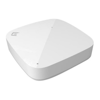
Overview of the WS-AP3805
The WS-AP3805 is designed to extend your IdentiFi
Wireless LAN around indoor locations. The WS-AP3805
supports the 802.11ac wireless standards, with full backward
compatibility with legacy 802.11a, 802.11b, 802.11g, and
802.11n devices. The WS-AP3805 interoperates fully with
other IdentiFi Wireless products and features including
support for VoWLAN, branch office mode, guest services,
RTLS, availability, and mobility features.
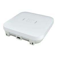
WS-AP3805 Features
• Radios: 2 radios (2.4 GHz and 5 GHz)
• LEDs: 3 (see Figure 2)
• Max. Power Consumption: 9.6W; 802.3af (see Tab l e 1 )
• Antennas:
– WS-AP3805i: 4 internal single band antenna
assemblies
– WS-AP3805e: 4 external RSMA antenna connectors
(external antennas must be ordered separately)
Items Shipped with the WS-AP3805
• T-rail Mounting Hardware:
– (2) 15/16” clips, and (2) 9/16” clips
– (2) Spacers
– Mounting screws
• Wall/Ceiling Mounting Bracket
• Mounting Bracket Hardware:
– (2) Drywall anchors
– Mounting screws
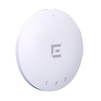
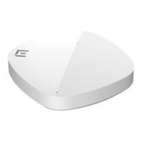
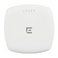
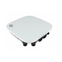
WS-AP3805 Views
Figure 1, shows both the front and back views of the WS-
AP3805.
Figure 1 Front & Back Views of the WS-AP3805
Note: The WS-AP3805 is available in both an “i” model
(with internal antennas) and an “e” model (with external
antennas). In this Quick Reference, any reference to
WS-AP3805
applies to both models.
1 Antenna Port, Radio 1 - Right
(5.0 GHz, AP3805e only)
6 External Antenna (1 of 4),
AP3805e only
2 Antenna Port, Radio 2 - Right
(2.4 GHz, AP3805e only)
7 External Power Supply
Port
3 Antenna Port, Radio 2 - Left
(2.4GHz, AP3805e only)
8 LAN port
4 Antenna Port, Radio 1 - Left
(5.0 GHz, AP3805e only)
9 Kensington Lock Slot
5 LEDs (see Figure 2)
Ta b le 1 shows ways to power the WS-AP3805.
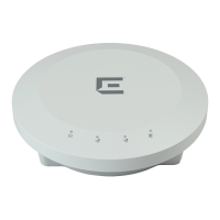
Figure 2 shows the LEDs on the front of the WS-AP3805.
Figure 2 LEDs on AP Front Face
Green LEDs mean ON. Amber LEDs mean OFF.
For detailed installation information about the WS-AP3805,
see the Extreme Networks IdentiFi Wireless WS-AP3805
Installation Guide.
Mounting and Connecting the AP
A wall mount bracket is included for quick and easy
mounting of the WS-AP3805 to a wall. Additionally, a
ceiling mounting kit is provided for mounting the AP to a
drop ceiling. Use these instructions as guidelines for
mounting and connecting the WS-AP3805 easily and
safely.
Table 1 Powering the WS-AP3805
Power
Source
Description
Power over
Ethernet
(PoE)
Power is provided through the RJ45 Ethernet port
(LAN port) on the top of the WS-AP3805. This is
the preferred method of powering the AP on ceiling
and high wall installations.
External 12V
DC power
supply
(optional)
The WS-AP3805 can also be powered by an
external DC power supply plugged into an AC
source. Plug the supply’s input jack into the DC-In
port (see Figure 1).
1 Power 3 Radio 2
2 Radio 1
Electrical Hazard: Only qualified personnel should perform
installation procedures.
Mounting on a Drop Ceiling
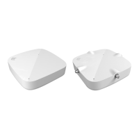
Figure 3 and Figure 4 shows the T-rail connector being
mounted to the WS-AP3805.
Figure 3 Attaching the T-Rail Connector to the AP
1 Attach the T-rail connectors (see Figure 3, Item 2) to the
bottom cover of the AP using the provided short screws
(see Figure 3, Item 1). Two sizes of T-rail connectors are
included in the mounting hardware kit: 15/16 in (2.38 cm)
and 9/16 in (1.43 cm).
2 If extra space is required to accommodate drop ceiling
tiles, use the provided spacers and long screws (see
Figure 3, Items 1 and 3).
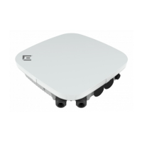
3 Remove the ceiling panels around the drop ceiling T-bar
rails where you intend to mount the AP.
4 Line up the connected T-rail connectors (see Figure 4,
Item 2) with an appropriately sized rail (see Figure 4,
Item 1), and press the AP onto the rail until it snaps into
place as shown in Figure 4.
5 Verify that the Ethernet cable that will connect to the AP
can reach the AP at the point where you plan to mount it.
6 With both bracket tabs over the T-bar rail lips, tap the AP
to verify it is stable and won’t fall off. Figure 4 illustrates
the AP and bracket mounted on a T-bar rail.
Figure 4 WS-AP3805 Mounted on Drop Ceiling T-bar
Rail
7 Make a hole through the ceiling panel closest to the
power slot on the AP. Run the Ethernet cable through the
hole and into an RJ45 LAN port in the recessed
connector bay.
8 Replace the displaced ceiling panels.
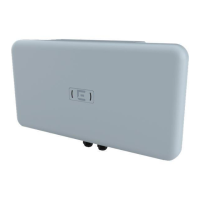
Mounting on a Wall or Solid Flat Ceiling
Figure 5 shows the AP3805 mounted to a wall or solid
ceiling.
Figure 5 Mounting the WS-AP3805 to a Flat Wall or
Solid Ceiling
1 Determine the spot on the wall where the AP is to be
mounted, preferably high up on the wall (near the ceiling
for maximum radio wave dispersion) but in reach of the
Ethernet cable and a wall power outlet if you are not able
to use Power over Ethernet.
2 Drill two holes in the wall (see Figure 5, Item 1) to match
the center of the two keyhole slots in the back of the AP
bracket (see Figure 5, Item 3).
3 Screw the anchors (see Figure 5, Item 2) into the holes
until they are flush with the wall, and screw the provided
mounting screws (see Figure 5 Item 5) into the anchors.
4 Screw the AP mounting screws (see Figure 5, Item 4)
into the bottom of the AP.
5 Mount the AP on the mounting bracket by aligning the
mounting screw with the slots in the bracket and rotating
the unit clockwise about 90 degrees to secure it in place.
Connecting a Power Supply to the WS-AP3805
If you need to power the WS-AP3805 with an external 12V
DC power supply, you can plug the power cord into the
power connector (see Figure 1, Item 6) on the back of the
AP. There is no wall mount for the 12V DC power supply.
Refer to the Extreme Networks IdentiFi Wireless WS-
AP3805 Installation Guide for information about the power
supply.
LAN Connection
The WS-AP3805 has one LAN (Ethernet) port (see Figure 1,
Item 7). During administration and maintenance through
the LAN, the AP must still have a power connection
through either an Ethernet PoE cable or a DC power supply.
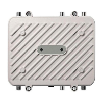
External Antennas (WS-AP3805e Only)
Install the external antennas intended for area coverage.
For information about antenna selection and installation,
refer to the Extreme Networks IdentiFi Wireless WS-
AP3805 Installation Guide.
Note: When drilling the holes for the wall anchors, the hole
diameter should be slightly smaller than the diameter of the
wall anchors provided.
Electrical Hazard: Do not connect the WS-AP3805 to an
external power supply if the AP is plugged into the PoE
port.
Note: LAN connectors with shrouds will not fit into the AP
port. Remove the shroud or use an optional jumper cable.