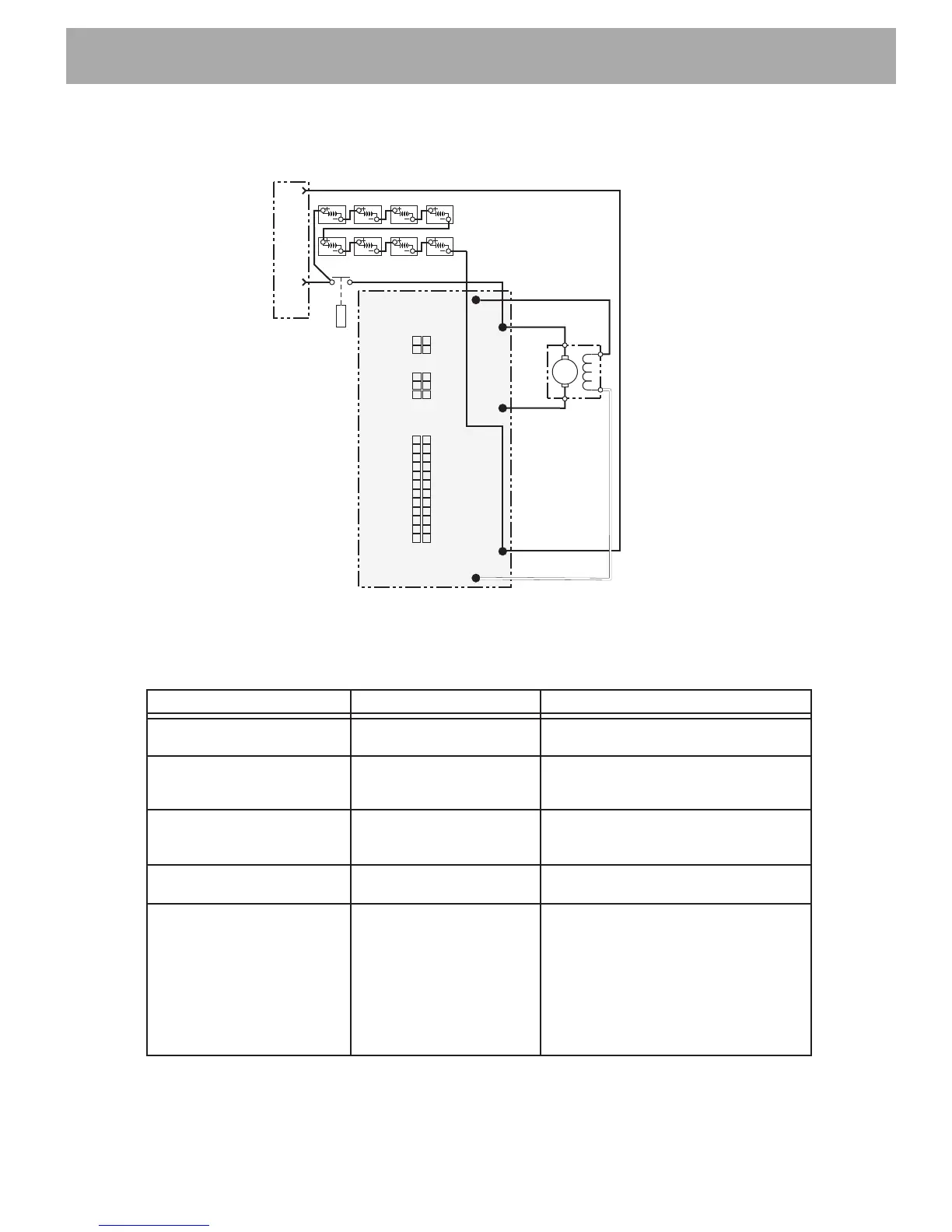
Fig. 14 Secondary Wiring Diagnostics
1
2
3
4
5
6
7
8
9
10
11
12
13
14
15
16
17
18
19
20
21
22
23
24
J1
A2
A1
F1
F2
Motor
WHT
BLK
BLK
1264 Controller
F2
B+
M-
B-
F1
Solenoid
Charging
Connector
48 Volt Battery Pack
J3
J2
4
5
6
1
2
3
This test will verify secondary circuit voltage. Please reference the chart for probe connections.
Probe Connection Voltage
If not/ Then
Positive prove on BL+ and
negative probe on BL-
BRF preferably 48 Volt Perform battery discharge test.
Verify the chrager/process
Negative probe on BL- and
positive probe on battery
side of solenoid
BRF Verify wire/connection quality
Positive probe on B+ and
negative probe on B-
BRF Verify solenoid function. Check wiring.
Negative probe on BL- and
positive probe on solenoid B+
BRF with solenoid engaged Verify primary voltage at Pin 5 & 17.
If BRF is found on the primary
terminals, replace solenoid.
Positive probe on B+ and
negative probe on M-
1-48 Volt depending on
performance plug
To verify: engage solenoid at high
pedal. Voltage should start around
1-2 volt. As the pedal is slowly
depressed to the floor, voltage should
rise to around 48 volt. If extremely low
voltage is observed, replace the
controller. If immediate high voltage is
observed, replace the motor.

 Loading...