Page G-3
Repair and Service Manual
B
B
MOTOR
Read all of Section B and this section before attempting any procedure. Pay particular attention to Notices, Cautions, Warnings and Dangers.
If brushes are to be replaced, proceed now to ‘Brush Replace-
ment’ before installing the armature.
For proper location, the armature has a positive stop
feature.
When installing armature into the bearing/end cover
assembly, support the bearing’s inner race to avoid dam-
age.
Press the armature into the new bearing using moderate
heat to aid installation.
Release brushes against commutator. Ensure the
springs are seated against the rear of the brushes and
are able to move freely.
Field Coil Replacement
Tool List Qty.
Wrench, 1/2"................................................................ 1
Ratchet, 3/8" drive....................................................... 1
Socket, 1/2", 3/8" drive ................................................ 1
To replace field coil (8), remove field coil terminal hard-
ware (9) at S1 and S2 (Ref. Fig. 3).
Remove bolts (10) that secure field coil retainers (11) to
motor housing (4). Remove the field coils.
Replacement field coils are installed in reverse order of
disassembly.
Brush Replacement
Tool List Qty.
Wrench, 1/2"................................................................ 1
Ratchet ........................................................................ 1
Socket, 5/16" ............................................................... 1
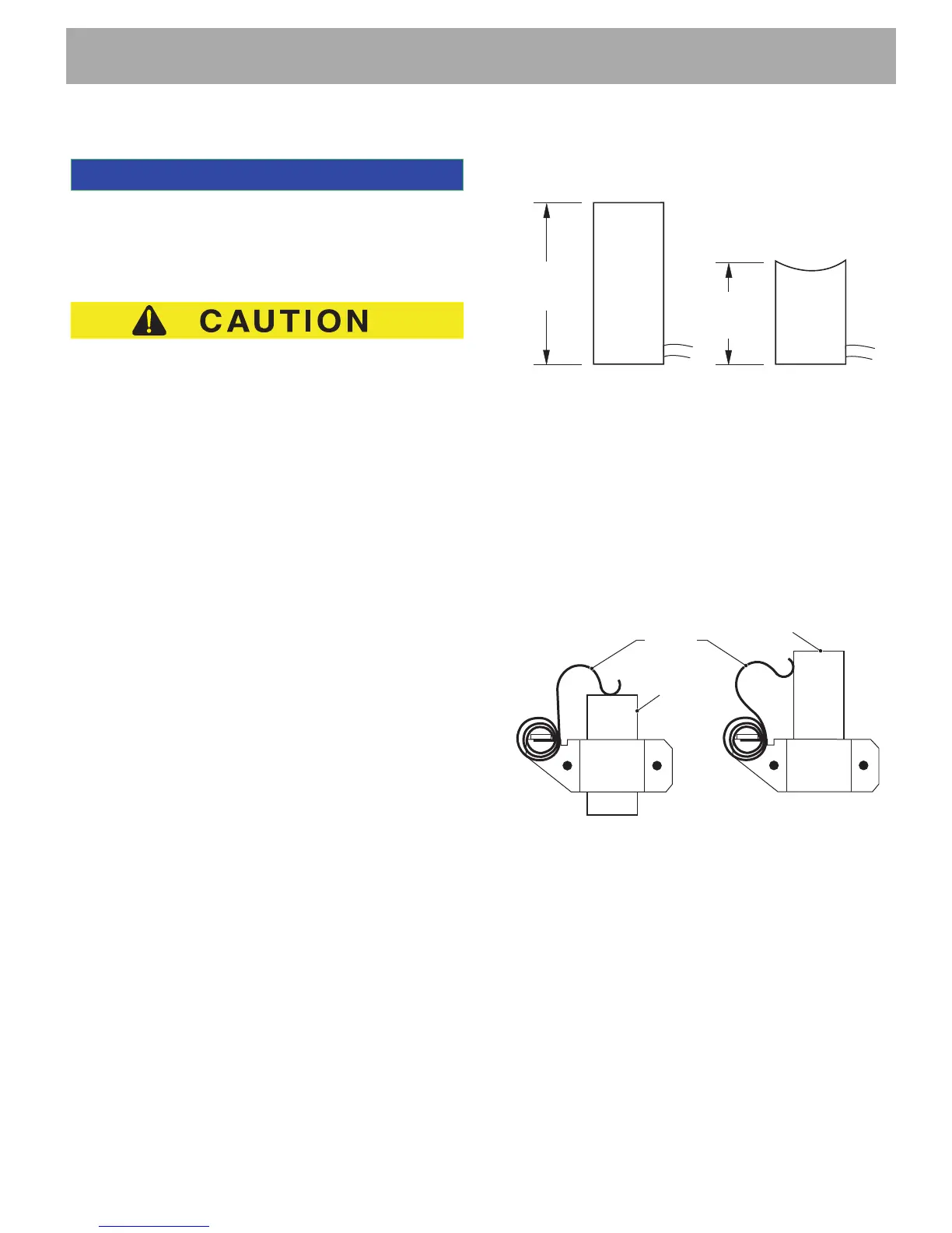
Brushes should be measured as shown and replaced
when the minimum dimension of .62" (16 mm) is
reached (Ref. Fig. 4).
Fig. 4 Brush Wear
Remove brush terminal hardware (12) at A1 and A2
(Ref. Fig. 3).
Remove screws (13) securing brush plate (14). Remove
brushes, rigging and brush plate.
Pull back each brush until each of the springs (15) rest
against the side of its brush (Ref. Fig. 5). Remove
brushes and replace with new brush replacement kit.
Locate springs against the side of each brush.
Fig. 5 Securing Brushes
Install terminals and brush plate using reverse order of
removal. Install armature (commutator end) through
brush plate and press into new bearing using moderate
heat to aid installation. Position brushes against commu-
tator. Ensure the springs are seated against the rear of
the brushes and are able to move freely.
Motor Assembly
Tool List Qty.
Socket, 3/8" .................................................................1
Torque wrench, in. lbs..................................................1
.62" Min
(16 mm)
1.30"
(33 mm)
New Brush Worn Brush
(Replace)
Brush
Brush
Spring
Spring Position
for Installed Brushes
Spring Position for
Removing/Replacing
Brushes
Brush

 Loading...