K P
ELECTRONIC DEADB LT LOCKO
1
2
3
4
5
6
7
8
9
0
USER MANUAL
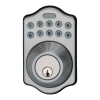
Product : KEYPAD ELECTRONIC DEADBOLT LOCK
Purchase Date :
Limited Warranty Statements
1. Warranty
Tong Lung Metal Industry Co., Ltd. (hereafter “TL”) warrants the Product to be free
from defects in material and workmanship for a period of 12 months
from the original date of purchase.
If you discover a defect in the Product covered by this warranty, we will repair or
replace the item at our option using new or refurbished components.
2. Exclusions
This warranty covers defects in manufacturing discovered while using the
Products as recommended by TL rather than occurred by the act of God,
and damages caused by misuse, abuse, and unauthorized modification.
3. Limited of Liability
TL will not be held liable for incidental or consequential losses or damages
to any act of God.
4. Reminder
Service requirement shall subject to the presentation of this warrant card
and defective parts to the manufacture TL.
The warranty card will not be reissued if lost.
TONG LUNG METAL INDUSTRY CO., LTD.
62, Chung Hsiao 1st Street, Hou-Hu-Li, Chia-Yi 600. Taiwan, R.O.C.
TEL : 886-5-2770017 FAX : 886-5-2767392
TEMPLATE
45 40 35
1-3/4" 1-9/16" 1-3/8"
Fit here on door edge
FOR BACKSET 70mm (2-3/4”)
FOR BACKSET 60mm (2-3/8”)
51
2"
Mark Ø1" (25.4mm) hole at
center of door edge.
Ø54mm (2-1/8")
Attention : Please do not use the "electronic" screwdriver for installation.