10
ENGLISH ENGLISH
These instructions apply to the following models:
FAAC 540 and FAAC 541
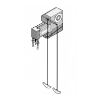
The 540 and 541 automated systems are designed for
automating balanced industrial sectional doors.
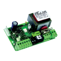
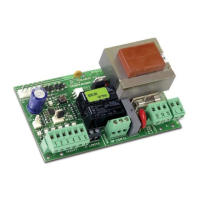
They consist of an electro-mechanical operator, and either on-
board electronic control equipment (540) or an interconnection
board for a remote control equipment (541). Installation is
possible either directly on the shaft of the rope-winding drums,
or by chain transmission (optional item) with a reduction ratio of
1:1.5 or 1:2.
The non-reversing system ensures mechanical locking of the door
when the motor is not operating and, therefore, no lock needs
to be installed; the manual release and the manual opening
system (in models for which it is supplied) make it possible to
move the door in case of a power cut or malfunction.
The 540 and 541 automated systems were designed and built for
indoor and outdoor use.
2. DIMENSIONS AND DESCRIPTION
AUTOMATED SYSTEM 540-541
1. TECHNICAL SPECIFICATIONS
Power supply (Vac 50-60Hz) 230 (+6 –10%)
Electric motor single-phase induction 1450rpm
Maximum absorbed power (W) 800
Absorbed current (A) 3,5
Starting capacitor (µF) 20
Winding thermal protection (°C) 140
Use frequency (S3) 40%
Max number consecutive cycles 5
Power take-off Hollow through shaft diam. 25,4mm (1'’)
Power take-off rotation speed (rpm) 23
Rated torque of power take-off (Nm) 50
Power take-off max revs 24
Protection class IP54
Operating ambient temperature (°C) -20 / +55
Gearmotor max weight (Kg) 14
Type of oil FAAC XD220
Oil quantity (l) 0,9
Note: consult Table 1 for chain transmission applications
Fig. 1
Graph 1 shows with which type of application the 540 can be installed,
considering the maximum force required to manually move the door F, in daN
(1daN = force required to lift 1,02 kg), and the diameter of the rope-winding
drum Df in millimetres. For example, if a door can be moved with a force of
60daN and the drum diameter is 170 mm, a 540 with chain transmission of 1:1.5
must be installed.
N.B. Force F can be measured with a dynamometer. It is not directly related to
the weight of the door, but to its balance.
0
20
40
60
80
100
120
140
160
180
100 120 140 160 180 200 220 240
Dt[mm]
F[daN]
Transmission
1:2
Transmission
1:1.5
Direct application
Graph 1
Table 1
Type of Rated Rope shaft Rope shaft
application torque speed max revs
(Nm) (rpm)
Direct 50 23 24
Reduction ratio 1:1.5
75 17,2 18
Reduction ratio 1:2
100 11,5 12