Do you have a question about the FAAC 531R and is the answer not in the manual?
Details electrical and operational specifications of the 531R control unit, including power, temperature, and fuses.
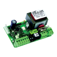
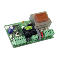
Identifies physical components, connectors, and switches on the 531R control board, referencing Fig. 1.
Explains the functions of terminal boards J1, J3, J10, and programming dip-switches DS1 on the 531R control board.
Describes the meaning of the status LEDs (LD1, LD2, LD3) indicating input states for the automated system.
Refers to main instructions for connecting safety devices, with no changes specified for the 531R operator.
Details the procedure for learning up to 10 radio codes using the control board's dip-switches and courtesy light.
Explains how to program new radio codes using the remote control, requiring a previously known remote.
Provides instructions for clearing all previously learned radio codes from the 531R control board's memory.
Specifies that only T4 LC 433 MHz remote controls should be used for operating the 531R.
States the 531R control board's compliance with relevant EEC directives and standards for safety and EMC.
The FAAC 531R control unit, designed for 531R and 531K operators, is an integrated system for automated gate control. It features a built-in 433 MHz receiver, enabling remote control of gate opening and closing without the need for external radio receivers.
The DS1 dip-switches allow configuration of various functions:
The control unit features LEDs to indicate the status of various inputs:
The status when the automated system is stopped and at rest is indicated in bold for each input.
A flashing light cannot be connected to this operator.
No changes are required for the connection of safety devices. Refer to the main instructions of the 531 EM operator for details.
The 531R control board can store up to 10 radio codes. If more remote controls (T4 LC) are added beyond this limit, the oldest radio codes will be overwritten.
This procedure can only be activated with remote controls already known to the 531R board.
This procedure deletes all radio codes stored in the memory.
For remote control of the 531R operator, only T4 LC remote controls should be used.
For any aspects not explicitly specified in these instructions, consult the instructions of the 531 EM operator.
| Brand | FAAC |
|---|---|
| Model | 531R |
| Category | Control Unit |
| Language | English |