12
ENGLISH
5.3. ADJUSTING END STOP SCREWS
Adjust the position of the beam in the maximum opening
and closing positions by setting the end stop screws as
shown in fig. 9.
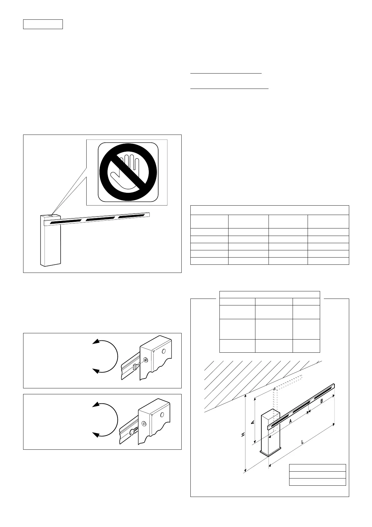
5.4 TESTING BARRIER UNIT
Once installation is complete, affix the danger warning
adhesive on the top of the housing (fig. 10).
Carry out a thorough functional check of the barrier unit
and all accessories connected to it. Give the page entitled
“End-user guide” to the customer and demonstrate how
to operate the barrier correctly, drawing the customer’s
attention to the points of potential danger.
BLOCCA / LOCK
BLOQUE / VERRIEGELT
BLOQUEAR
BLOCCA / UNLOCK
DEBLOQUE / ENTRIEGELT
DESBLOQUEAR
BLOCCA / LOCK
BLOQUE / VERRIEGELT
BLOQUEAR
SBLOCCA / UNLOCK
DEBLOQUE / ENTRIEGELT
DESBLOQUEAR
fig. 11-A
fig. 11-B
6. MANUAL OPERATION
If the barrier needs to be operated manually as a result of
a power failure or malfunction, use the unlock device as
follows.
The key provided can be triangular (standard) or
personalised (optional).
- Insert the standard key (fig. 11-A) or the personalised key
(fig. 11-B) in the lock and turn anticlockwise by one
revolution.
- Open or close the barrier manually.
fig. 10
7. RETURNING TO NORMAL OPERATION
To prevent an accidental impulse from activating the
barrier, turn off the system’s electrical power supply before
returning to normal operation.
triangular key (standard):
- turn the key clockwise until it stops, then remove it.
personalised key (optional):
- turn the key clockwise until it stops.
- turn the key anticlockwise very slowly to the point where
it can be removed.
8. BALANCE SPRINGS
The 630 barrier unit requires a beam balance spring which
must be ordered separately. The spring varies according
to the length and type of beam (rigid, with skirt or
articulated).
Refer to the tables below to determine the type of spring
required.
8.1. SPRINGS FOR RIGID BEAMS AND BEAMS WITH SKIRTS
Table 2
BALANCE SPRING
Ø
rigid beam with
code
beam skirt
5.5 up to 2.5 m up to 2.5 m 721008
6 2 ÷ 2.5 m 721005
6.5 2.5 ÷ 3 m 2.5 ÷ 3 m 721013
7 3 ÷ 4 m 721006
7.5 3 ÷ 4 m 721007
A = H - 780 mm
B = L - A
A MAX= 2250 mm
8.2. SPRINGS FOR ARTICULATED BEAMS
Table 3
Balance spring table
L (mm) A (mm) code
Up to 2000
1000 ÷ 1500 721008
1500 ÷ 2000 721005
1000 ÷ 1500 721008
2000 ÷ 3000 1500 ÷ 2000 721005
2000 ÷ 2250 721013
3000 ÷ 4000
1000 ÷ 2000 721013
2000 ÷ 2250 721006
 Loading...