EasyManua.ls Logo

FAAC 630 User Manual

FAAC 630
9 pages
To Next Page IconTo Next Page
Page #1 background imageLoading...
Page #1 background image
1
ENGLISH
CE DECLARATION OF CONFORMITY FOR MACHINES ................................................................................................. 2
WARNINGS FOR THE INSTALLER ................................................................................................................................. 2
1. DESCRIPTION AND TECHNICAL SPECIFICATIONS ................................................................................................... 3
1.1 MAXIMUM USE CURVE ............................................................................................................................................. 4
6 MANUAL MODE OPERATION .................................................................................................................................. 7
7 RESTORING NORMAL OPERATION MODE ................................................................................................................ 7
8 MAINTENANCE ...................................................................................................................................................... 7
8.1 TOPPING UP OIL ...................................................................................................................................................... 7
8.2 BLEEDING OPERATION ............................................................................................................................................. 7
9 REPAIRS ................................................................................................................................................................. 8
10 CHANGING THE RH (LH) VERSION OF THE BARRIER INTO THE LH (RH) VERSION ...................................................... 8
11 AVAILABLE ACCESSORIES .................................................................................................................................... 8
12 DETAILED TECHNICAL SPECIFICATIONS ................................................................................................................. 10
INDEX
2 ELECTRIC PREPARATIONS (standard system) ..........................................................................................................4
3 DIMENSIONS ......................................................................................................................................................... 4
3.1 BARRIER 630.................................................................................................................................................... 4
3.2 BARRIER 630 PLUS - 640..................................................................................................................................4
4 INSTALLING THE AUTOMATED SYSTEM....................................................................................................................4
4.1 PRELIMINARY CHECK..............................................................................................................................................4
4.2 MASONRY FOR FOUNDATION PLINTH......................................................................................................................4
4.3 MECHANICAL INSTALLATION ..................................................................................................................................5
4.3.1 BARRIER 630...................................................................................................................................................5
4.3.2 BARRIER 630 PLUS - 640................................................................................................................................6
4.4 ADJUSTING THE BALANCING SPRING.......................................................................................................................6
5 START-UP ................................................................................................................................................................. 6
5.1 CONNECTION TO CONTROL BOARD ....................................................................................................................... 6
5.2 ADJUSTING THE TRANSMITTED TORQUE .................................................................................................................... 6
5.3 ADJUSTING THE TRAVEL LIMIT SLOW DOWN ............................................................................................................. 6
5.4 AUTOMATED SYSTEM TEST ........................................................................................................................................ 7
Question and Answer IconNeed help?

Do you have a question about the FAAC 630 and is the answer not in the manual?

FAAC 630 Specifications

General IconGeneral
Max leaf length3 m
Hydraulic lockingYes
Weight7.5 kg
Power supply voltage230 Vac (+6% -10%) 50 Hz
Operating ambient temperature-20°C to +55°C
Operating Voltage230 Vac (+6% -10%) 50 Hz

Summary

WARNINGS FOR THE INSTALLER

GENERAL SAFETY OBLIGATIONS

Key safety guidelines and precautions for installers, covering electrical safety, environmental hazards, and proper use.

AUTOMATED SYSTEM 630 - 630PLUS - 640

DESCRIPTION AND TECHNICAL SPECIFICATIONS

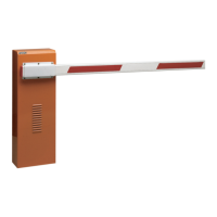
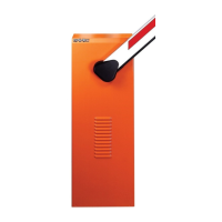
Overview of the automated system, its components, and detailed technical data for different models.

Technical Specifications Table

A table summarizing key technical parameters for 630, 630 PLUS, and 640 barrier models.

1400 RPM Electric Motor Details

Technical specifications for the 1400 RPM electric motor used in the system.

2800 RPM Electric Motor Details

Technical specifications for the 2800 RPM electric motor used in the system.

MAXIMUM USE CURVE

Understanding Use Frequency

Explains how to interpret the use frequency graph and calculate the percentage of effective work time.

ELECTRIC PREPARATIONS

Standard System Wiring

Illustrates standard electrical connections for accessories like photocells, radio receivers, and push-buttons.

BARRIER DIMENSIONS

Barrier 630 Dimensions

Provides detailed dimensional drawings and specifications for the FAAC 630 barrier model.

Barriers 630 PLUS - 640 Dimensions

Provides detailed dimensional drawings and specifications for the FAAC 630 PLUS and 640 barrier models.

INSTALLING THE AUTOMATED SYSTEM

Preliminary Checks for Installation

Essential checks required before system installation, ensuring safety and proper foundation.

Masonry for Foundation Plinth

Instructions for creating the foundation plinth and preparing the wall for the barrier hatch.

MECHANICAL INSTALLATION

Barrier 630 Mechanical Installation

Step-by-step guide for installing the barrier upright, beam, and setting mechanical stops for the 630 model.

Adjusting the Balancing Spring

Procedure for fine-tuning the barrier's balancing spring to ensure the beam stays idle at 45 degrees.

START-UP PROCEDURES

Connection to Control Board

Important safety note to turn off power before connecting the control board.

Adjusting Transmitted Torque

Instructions for adjusting the by-pass screws to set opening and closing movement torque.

Adjusting Travel Limit Slow Down

Guide to adjusting travel limit cams and control unit slow-down time for beams over 4 meters.

AUTOMATED SYSTEM TEST

Post-Installation Checks

Applying danger stickers and checking the operational efficiency of the automated system and accessories.

MANUAL MODE OPERATION

Manual Barrier Movement

Procedure for manually moving the barrier using the release key during power cuts or system faults.

RESTORING NORMAL OPERATION MODE

Activating Locking System

Steps to restore normal operation by activating the locking system, with safety precautions.

MAINTENANCE

Periodic Maintenance Checks

Check settings of by-pass screws, system balancing, and efficiency of safety devices during 6-monthly maintenance.

Topping Up Oil

Procedure for checking and topping up hydraulic oil level using specified FAAC HP OIL.

BLEEDING OPERATION

Hydraulic System Air Bleeding

Procedure to bleed air from the hydraulic system for correct beam movement.

REPAIRS

Contacting Authorized Repair Centres

Recommendation to contact FAAC's authorized repair centres for any necessary repairs.

CHANGING THE RH (LH) VERSION OF THE BARRIER

Converting RH to LH Version

Detailed procedure for converting a Right Hand (RH) barrier version to a Left Hand (LH) version.

AVAILABLE ACCESSORIES

Anti-Vandal Valve

Protects the hydraulic system if the beam is forced, preventing damage.

Automatic Emergency Release

Allows manual beam lifting during power cuts without accessing the hydraulic control unit.

Fork Support

Prevents beam bending and splitting, and allows it to rest when closed.

Skirt Kit

Increases beam visibility; may require balancing spring adaptation.

Articulation Kit

Allows articulated rigid beam for maximum ceiling height; may require spring adaptation.

End Foot

Allows beam to rest when closed, preventing downward profile bending; may require spring adaptation.