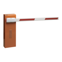
B
A
D
C
B
A B
C
D
ENGLISH
1) Fasten the upright on the foundation plate using the four
supplied nuts (fig.8) and checking the configuration of the
barrier as in figure 7.
Remember that the hatch of the upright should normally
face the building.
2)
Set the operator for manual operation as described in chapter 6.
3) Remove and store the breather screws as shown in Fig.9.
4) Assemble the beam, using the supplied screws, as shown in
figures 10 or 11 (The rubber profile of the beam must face
in closing direction).
5) Adjust the opening and closing travel limit mechanical stops
as per fig.12
. and verify beam balancing following the
instructions in paragraph 4.4.
1) Assemble the foundation plate as in fig.6. ref.
2) Make a foundation plinth as shown in fig.4 ref.
b (referred to
clayey soil)
3) Wall the foundation plinth as shown in fig.6, ref.
b, supplying
one or more sheaths for routing electrical cables. Using a
spirit level, check if the plate is perfectly level. Wait for the
cement to set.
Fig. 6
Fig. 7
4.3 MECHANICAL INSTALLATION
Fig. 9
Fig. 8
Fig. 10
When the barrier
is open, the spring
MUST NOT be
compressed
RH LH

 Loading...