2
XP15B
37 mm.
105 mm.
26 mm.
Ø16 mm. Max
Ø16 mm. Max
햲햲
햲햲
햲
햲햲
햲햲
햲
Fig. 1
Fig. 3
Fig. 2
1. DESCRIPTION AND TECHNICAL SPECIFICATIONS
ylppusrewoP
,ysaE2SUBmorf
V42owthtiw
desiralopnon
seriw
)Am(noitprosbA
01
).m(yticapacmumixaM
51
ssalcnoitceto
rP
45PI
)cesm(emitnoitcetedelcatsbO
02
dohtemtnemngilA
citamotua
elgnatnemngila-fleS
).m51(°7-/+
).m5(°31-/+
)
C°(erutarepmettneibmagnitarepO
55+/02-
noitallatsnI
llaw-no
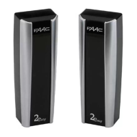
The self-aligning photocell XP15B with connection to
BUS 2 easy, consists of a transmitter and a receiver with
synchronised infra-red rays.
The XP15B photocell is an additional safety device.
If the light beam is shadowed, this causes the receiver
to change its status. The receiver sends the photocell
engaged signal via the BUS.
The two BUS connection terminals are interchangeable
and, therefore, the connection polarity need not be
observed.
2. DIMENSIONS
3. INSTALLATION
For best operation, position the Receiver and
Transmitter aligned.
Two types of installation are possible:
- On-wall with embedded pipe (Fig.2).
- On-wall with external pipe/sheath (Fig.3).
•Make the preparations for the electrical connections.
•Fasten the containers, using suitable screws and
expansion plugs.
•When installing, use the rubber separator (ref.
햲햲
햲햲
햲 of
Fig.2 and Fig.3) to protect the electronics of the
photocell against dust and/or insects.
Photocell XP15B can be connected only to
FAAC control units which control the BUS 2 Easy line.
Up to 16 pairs of photocells can be connected
to each system. To select the type of safety device,
refer to the instructions of the control unit.

 Loading...