1
0
70
32,5
90
105
98
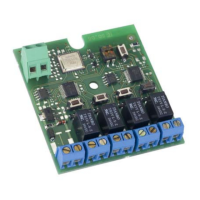
CH1 CH2 CH3 CH4
5
DL1
DL2 DL3 DL4
SW1
SW2 SW3 SW4
SW5
DS1
DL6
12
6
7
8
14
9
10
11
12
13
1
2
3
4
N.O. N.O. N.O. N.O.
DL5
+
FRANÇAIS
2 CARACTÉRISTIQUES TECHNIQUES
XR4 433 C - XR4 868 C
XR4 433 C XR 868 C
ALIMENTATION (V) 12 ÷ 24 ca-cc 12 ÷ 24 ca-cc
FRÉQUENCE DE RÉCEPTION (MHz) 433.92 ±0.1 868.35±0.2
COURANT ABSORBÉ (mA) 100 mA 100 mA
DÉCODAGE (SYSTÈME OMNIDEC) DS-LC-SLH DS-SLH
CODES MÉMORISABLES 250 CH1-2 / 250 CH 3-4 250 CH1-2 / 250 CH 3-4
NOMBRE DE CANAUX 44
NOMBRE DE SORTIES À RELAIS (N.O.)
N 2 impulsives (CH 1-3)
N 1 impulsive / fixe (sélectionnable)(CH2)
N 1 temporisée (CH 4)
N 2 impulsives (CH 1-3)
N 1 impulsive / fixe (sélectionnable)(CH2)
N 1 temporisée (CH 4)
PORTÉE CONTACT RELAIS 0.5 A / 120 VA 0.5 A / 120 VA
DEGRÉ DE PROTECTION IP 44 IP 44
TEMPÉRATURE D’UTILISATION (°C)
-20 / +55 -20 / +55
/Pré-cassure pour serre-câbles (Ø 16,5)
0Couvercle
1Disposition pour fixation sur guide DIN
2Pattes d’attache pour fixation avec des vis
3 Bornes pour sortie commande (N.O.)
4 Contact à relais normalement ouvert (N.O.)
5 LEDs de signalisation ( ON = SORTIE ACTIVE)
DL1=LED CH 1 DL2=LED CH2
DL3=LED CH3 DL4=LED CH4
6 Boutons-poussoirs de programmation radio
SW1=BOUTON-POUSSOIR CH1 SW2=BOUTON-POUSSOIR CH2
SW3=BOUTON-POUSSOIR CH3 SW4=BOUTON-POUSSOIR CH4
7
DL6: LED de signalisation de programmation du temps CH4
8
SW5: Bouton-poussoir de programmation du temps CH4
9DIP-SWITCHE de sélection
: Borne pour alimentation
; Borne pour antenne
< DL5: LED de présence de courant
(ON = PRÉSENCE DE COURANT)
1 DESCRIPTION
L’armoire électronique XR C est un récepteur externe à quatre canaux, munie d’un système de décodage intégré
(DS, SLH, LC), appelé OMNIDEC. À l’activation d’un canal par l’intermédiaire de la radiocommande (DS, SLH, LC), le
contact à relais N.O. respectif se ferme suivant les modalités décrites au chapitre 5.
Les configurations sélectionnables sont les suivantes :
CH1= sortie à relais N.O. à impulsion
CH2= sortie à relais N.O. à impulsion/fixe ( sélectionnable par l’intermédiaire de DS1 )
CH3= sortie à relais N.O. à impulsion CH4=
sortie à relais N.O. temporisée ( réglable par l’intermédiaire de SW5
)
Fig.1
CLIGNOTEMENT LENT
DL6
BASE DES TEMPS A PARTIR DE 30 S
SELECTIONNÉE ET SORTIE ACTIVE
CLIGNOTEMENT
RAPID DL6
BASE DES TEMPS À PARTIR DE 1 S
SÉLECTIONNÉE ET SORTIE ACTIVE
DS1 ON OFF
DIP
SWITCHE 1
SORTIE CANAL 2
FIXE
SORTIE CANAL 2
IMPULSIVE
DIP
SWITCHE 2
BASE DES TEMPS CANAL 4
1 SECONDE SELECT.
(VOIR CHAP. 6)
BASE DES TEMPS CANAL 4
30 SECONDES SELECT.
(VOIR CHAP. 6)
 Loading...