29
WARNING
To avoid injury or damage to the meter, make sure to
turn off all power and discharge all capacitors before
measuring continuity.
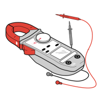
4.9 Frequency/Duty Cycle
1. Insert the red test lead in the “INPUT” jack and the
black lead in the “COM” jack.
2. Move the rotary switch to the “Hz%” position. Connect
the test leads across the circuit to be measured.
3. Read measured resistance on the display.
4. Read measured duty cycle on the display.
5. Specications
5.1 General Specications
• Safety rating: CAT III 600V
• Max. operating altitude: 2000m
• Operating temperature: 0~40°C, <80% RH
• Storage temperature: -10~60°C, <70% RH
(battery removed)
• Coefcient: 0.1 accuracy/°C
• Max. voltage between terminals and ground: 600V
DC or AC rms
• Sample rate: Approx. 3 times/sec
• Display: digit LCD (max. display: 5999/1999
(Resistance))
• Over-range indication: Display only shows “OL”
• Low battery indication: When battery voltage drops
below operating voltage,“ ”symbol appears on
the display
• Polarity indication: automatically displays “-”
• Power: 3x 1.5V AAA batteries
NU-712B_0618 7 langues.indd 29 22/06/2018 11:50:59