13
exp
Drwg. No.1643
28
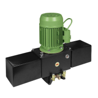
230V SINGLE-PHASE PROGRAMMER FOR SWING GATE
OPERATORS
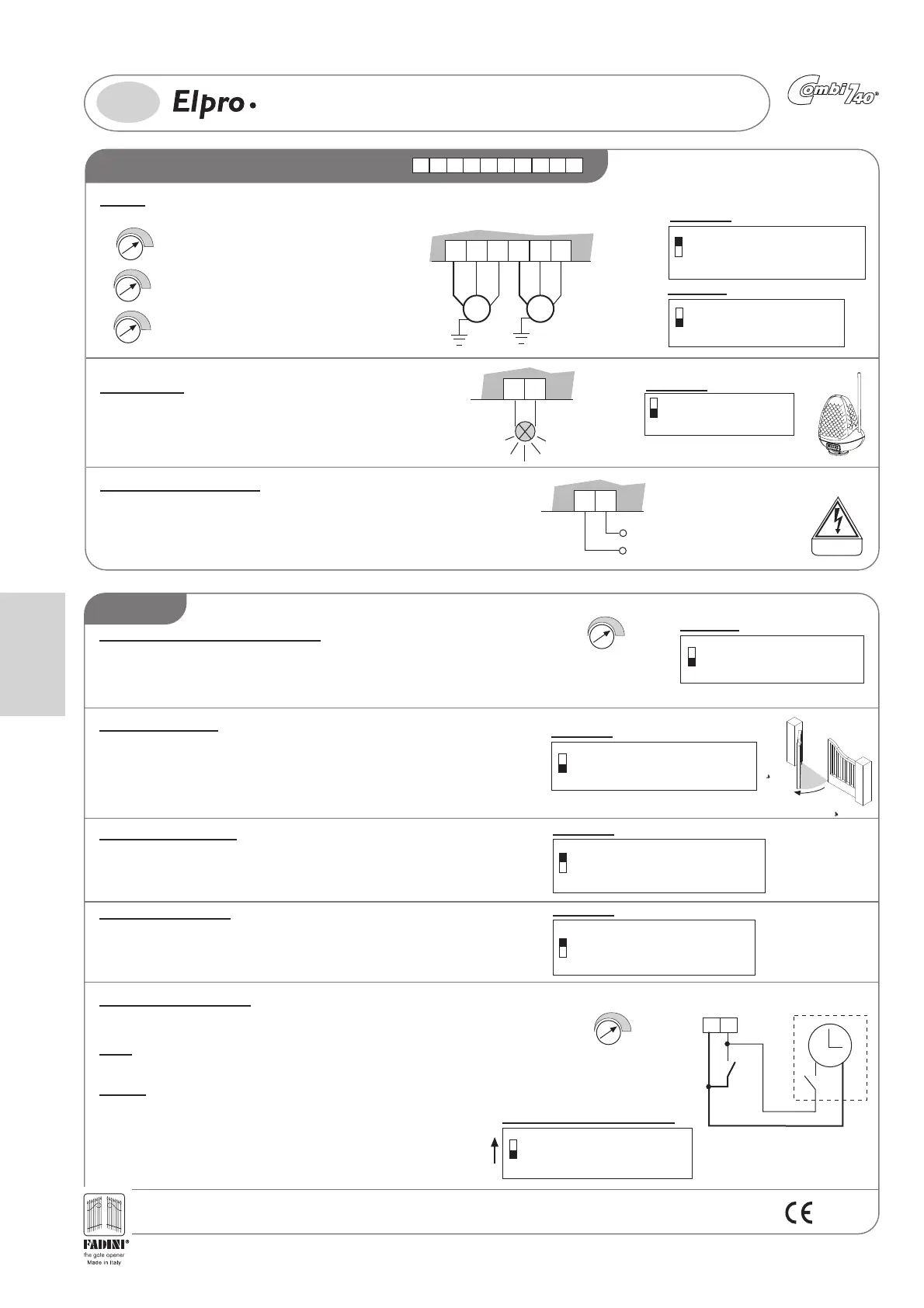
ELECTRIC POWER CONNECTIONS
Motors:
Programmer power supply:
Flashing light:
l'apricancello
211816 17 19 20 2422 23 25
-
+
CLOSING LEAF DELAY TIME
0s - 18s
-
+
DWELL TIME (If Dip-Switch 3=ON)
0s - 120s
-
+
OPERATING TIME
2s - 100s
Having terminated the electrical connections to the Motors, the three timers must be adjusted:
Leaf delay on closing, Dwell Time and Operating Time
MOTOR M1 OUTPUT
230V SINGLE-PHASE
(Motor for opening 1
st
leaf
and Pedestrian)
MOTOR M2 OUTPUT
230V SINGLE-PHASE
COMMON
21
M1 M2
18
16
17
19
20
COMMON
4
ON: Pre-flashing
OFF: Without pre-flashing
DIP-SWITCH 4:
22 23
FLASHING LIGHT
230V 25W max
24 25
POWER SUPPLY INPUT
SINGLE-PHASE 230V ±10% 50Hz
Apply a high sensitivity differential Thermo magnet circuit breaker type 0.03A to the
programmer’s power supply.
The card requires a 230V ±10% 50Hz single-phase power supply once all the low voltage and
power connections have been completed.
Stroke reversing pulse:
Automatic / Semi-automatic function:
Pedestrian opening:
Pedestrian opening of a completely closed gate leaf is obtained giving an Open command,
with Dip-Switch no. 6=ON, to terminals 3-4:
- a first opening command opens the Motor 1 leaf
- with a second command to terminals 3 and 4, the second leaf also opens.
The transmitter is always enabled for both leaves with Radio Contact 7-8
3
DIP-SWITCH 3
ON = Closes in Automatic mode
OFF = Does not close in Automatic mode
Semi-automatic function
Automatic cycle: when an open pulse is given, the leaves open, they stop in dwell for the time
set on the timer, after which they close automatically.
Semi-automatic cycle: when an open pulse is given, the leaves open. To close the leaves, give
the close pulse.
230 VOLT
-
+
DWELL TIME
0s - 120s
6
DIP-SWITCH 6:
ON= Single-leaf pedestrian service
OFF= Normal service
M1
Pre-flashing Dip-Switch 4=ON: Once the control pulse has been given the
flashing light switches on and the operator starts 3 seconds later.
8
DIP-SWITCH 8:
ON: Eliminates the Leaf delay when opening.
The motors start together
OFF: Leaf delay when opening enabled
3
DIP-SWITCH 3
ON = Closes in Automatic mode
OFF =Does not close in Automatic
mode Semi-automatic function
7
ON: Stroke reversing pulse function enabled
when opening from closed gate
OFF: Stroke reversing pulse deactivated
DIP-SWITCH 7:
Function (Dip-Switch no. 7=ON) that facilitates disengagement of the electric lock when the
gate is completely closed, even in Pedestrian Opening mode: with the gate leaves closed,
before opening they are pushed to close for 2 seconds.
Step-by-step function:
Dip-Switch no.5=ON At each pulse on the radio contact the gate performs open-stop-close-stop
5
ON: Step-by-step function enabled
OFF: Step-by-step function deactivated
DIP-SWITCH 5:
External clock (Optional):
DIP-SWITCH No. 3=ON Automatic Closing
3
ON = Closes in Automatic mode
OFF = Does not close in Automatic mode
Semi-automatic function
43
COMMON
COMMON
OPEN
NO
External clock
CLOCK: The Elpro 13 exp Programmer makes it possible to connect a normal clock for
opening-closing
Wiring: connect in parallel the NO contact of the Clock with terminal no. 4 OPEN and
no. 3 COMMON, activating automatic re-closing with the Dip-Switch no. 3=ON and
setting the dwell time on the trimmer
Operation: programme the opening time on the clock, at the time set the gate will open
and remain open (the flashing light switches off and the indicator light gives the signal
with two quick flashes followed by a longer dwell) and will not accept any further
command (including radio commands) until the time set on the clock has elapsed, at
the end of which, following the dwell time, automatic reclosure will take place.
-
+
DWELL TIME
0s - 120s
FUNCTIONS
GB
English
ELECTRICAL WIRING DIAGRAM OF COMBI 740 AND ACCESSORIES WITH ELPRO 13 exp
PIC. 22
29
DIP-SWITCH
ON
OFF
1 456 7823
11
12
13 14 15
1
74
10
2
85
3
96
21
M1 M2
18
16
17
19
20
SUPPORT FOR
PLUG-IN RADIO
CARD
-
+
CLOSING LEAF
DELAY TIME
0s - 18s
L1
L6
L3
L4
L5
L2
24
22
23
25
28
26
27
-
+
DWELL TIME
0s - 120s
-
+
OPERATING TIME
2s - 100s
TERMINAL BOARD FOR
CONNECTING THE PULIN 3
BUTTON SWITCH
230V – 24V
Transformer
12 345 45
FIT 55
Photocell
receiver
FIT 55
Photocell
projector
CHIS 37
key-switch
Plug-in RADIO
Jubi 433/2R
Miri 4
Flashing light
Birio A8 Aerial
Cable RG58
12
13
2
16
1
12 13
26 27 28 3
LED
Pushbutton switch
Pulin 3
3
4
56
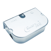
Programmer
housing
17 18
19 20 21
22 23
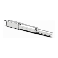
Combi 740
Motor M1
Combi 740
Motor M2
3
4
Pulin 3
pushbutton
switch
2322
3
24V Fuse
F5= 1A
Elpro 13 exp FADINI
Line fuse
F1= 5A
TUPTUO V42 Am052 rof .xam :daol
- 2
sriap
fo cirtceleotohp
sllec
reviecer oidaR 1 -
STOP CN
COMMON
NEPO ON
ESOLC ON
TCATNOC CN
SLLECOTOHP
RADIO ON
TCATNOC CN
2
nd
SLLECOTOHP fo riap
x
am W3 V42 thgil rotacidnI
NOMMOC
NOMMOC
COMMON
THGIL GNIHSALF
V0
32
W52
xam
230V 50Hz ±10% SINGLE-PHASE
POWER SUPPLY INPUT
12.5 µF
Capacitor
Motor M1
Line fuse
F2= 5A
Flashing light fuse
F3= 630mA
Transformer
fuse
F4= 630mA
Opening Delay
Relay
Closing Delay
Relay
Line relay
Motor M2
direction relay
REWOP AV51 ,CA V21
TUPTUO YLPPUS
Motor M1
direction relay
ESAHP-ELGNIS
V032
MOTOR
M2
ESAHP-ELGNIS
V032
MOTOR
M1
gninepo rof rotoM(
)nairtsedeP dna 1 etag
KCOL CIRTCELE
English
 Loading...