EasyManua.ls Logo

fadini Junior 624 - User Manual

fadini Junior 624
20 pages
Print Icon
To Next Page IconTo Next Page
Loading...
Dis. 6399
meccanica
FADINI
Via Mantova 177/A - C.P. 126 - 37053 Cerea (VR) Italy -
Tel. +39 0442 330422 - Fax +39 0442 331054 - info@fadini.net - www.fadini.net
I
Junior 624 - Junior 633 - Junior 650
IL PROGRAMMATORE È GIÀ COLLEGATO IN FABBRICA PER IL CORRETTO FUNZIONAMENTO DEI FINECORSA, PERTANTO NON INVERTIRE
MAI FILI O CONNETTORI GIÀ INSTALLATI E COLLEGATI DALLA DITTA COSTRUTTRICE.
INSTALLATO FISICAMENTE IL JUNIOR ALLA BASE DEL CANCELLO, PROSEGUIRE CON TUTTI I DIP-SWITCH IN OFF AD ESCLUSIONE DEL DIP-
SWITCH 11 CHE IDENTIFICA L'INSTALLAZIONE DESTRA O SINISTRA. SELEZIONARE PROGRESSIVAMENTE I DIP-SWITCH DELLE FUNZIONI SOLO
DOPO AVER LETTO E COMPRESO ATTENTAMENTE LE SINGOLE FUNZIONI SUL LIBRETTO ISTRUZIONI.
NON È GARANTITO IL FUNZIONAMENTO DEL JUNIOR CON ACCESSORI NON ORIGINALI FADINI: la certificazione secondo normative
EN 12445 e EN 12453 e' stata ottenuta con test di laboratorio con l'uso esclusivo degli accessori originali della MECCANICA FADINI.
In particolare il JUNIOR 624 deve essere installato solo con fotocellule FIT 55 o ORBITA 57.
DURANTE LA PROCEDURA DI APPRENDIMENTO (Fig.18-Fig.29 del Libretto Istruzioni) TUTTE LE SICUREZZE SONO DISATTIVATE
prestare quindi la massima attenzione affinchè non ci sia alcun transito nella zona di movimento del cancello.
LE ASOLE DI FINECORSA MAGNETICO HANNO I MAGNETI INTERNI GIÀ INSTALLATI CORRETTAMENTE SULLE STAFFE METALLICHE, NON APRIRLE
O INVERTIRE I MAGNETI.
DEVONO ESSERE INSTALLATE SUL LATO DESTRO E SINISTRO SULLA CREMAGLIERA, COME STAMPIGLIATO SULLA COPERTURA PLASTICA DELLE
STESSE (Fig.15 e Fig.16 a pag. 8 del Libretto Istruzioni), PENA IL NON FUNZIONAMENTO CORRETTO DELL'APRICANCELLO: IN TAL CASO
TOGLIERE IMMEDIATAMENTE IL FUSIBILE DI RETE DA 5A E RIPOSIZIONARE CORRETTAMENTE LE ASOLE.
PRIMA DI DARE TENSIONE VERIFICARE LA POSIZIONE DI MONTAGGIO DELL'APRICANCELLO "JUNIOR INSTALLATO DESTRO OPPURE SINISTRO"
VISTO ALL'INTERNO DEL CANCELLO DA MUOVERE.
Selezionare il Dip/Switch 11 a tensione assente (Fig. 4 a pag. 4 del Libretto Istruzioni): posizionare il cancello a metà corsa circa, tenere
premuto il pulsante di programmazione LP e dare tensione inserendo il fusibile di linea da 5A, quindi trascorsi 3 secondi rilasciare il
pulsante di programmazione, il led corrispondente lampeggia segnalando la modalità di apprendimento della corsa.
Premere con un impulso per far aprire il cancello e proseguire come descritto da Fig. 18 a Fig. 29 del libretto istruzioni.
IMPORTANTE: SE INVECE IL CANCELLO CHIUDE, TOGLIERE IL FUSIBILE DI LINEA DA 5A PER FERMARLO: SI E' VERIFICATO UN ERRORE DI
PARTENZA, SICURAMENTE NON SI E' SELEZIONATO LA CORRETTA INSTALLAZIONE DESTRA O SINISTRA CON IL DIP-SWITCH 11 A TENSIONE
ASSENTE. RIPETERE LA PROCEDURA PARTENDO DALL'INIZIO: IL PRIMO IMPULSO DI PROGRAMMAZIONE DEVE ESSERE SEMPRE IN APERTURA.
ALLA PRIMA ACCENSIONE VERIFICARE CHE I LED COLOR VERDE SIANO CORRETTAMENTE ACCESI; PROCEDERE POI SENZA DARE ULTERIORI
COMANDI ALLA VERIFICA DELLA LETTURA DEI FINECORSA: I LED X E Y DEI FINECORSA SI TROVANO SUL LATO DIETRO LA SCHEDA A FIANCO
IL CONNETTORE DEL FINECORSA (Fig.17).
IL DIP-SWITCH 10 DEL CONTROLLO "DSA" DELLE FOTOCELLULE DEVE ESSERE SELEZIONATO SOLO SE I TRASMETTITORI DELLE FOTOCELLULE
SONO ALIMENTATI ATTRAVERSO I MORSETTI DEDICATI 13-14 (Fig.17 DEL LIBRETTO ISTRUZIONI), PENA IL BLOCCO COSTANTE DEL CANCELLO.
!
GB
= IMPORTANTE
!
= IMPORTANT
!
Junior 624 - Junior 633 - Junior 650
THE CONTROL BOARD IS FACTORY PRE-WIRED FOR THE CORRECT FUNCTIONING OF THE LIMIT SWITCHES, NEVER CHANGE THE CONNECTIONS
OR CONNECTORS AS SET BY THE MANUFACTURER.
ONCE JUNIOR IS INSTALLED ON TO THE GATE, GO ON WITH ALL THE DIP-SWITCHES TO OFF, WITH THE EXCLUSION OF DIP-SWITCH 11 TO
BE SET TO THE INSTALLATION REQUIREMENTS EITHER RIGHT OR LEFT. THE DIP-SWITCHES ARE TO BE SET SO TO MEET THE APPLICATION
REQUIREMENTS, AFTER CORRECT UNDERSTANDING OF THEIR RESPECTIVE FUNCTIONS AS EXPLAINED IN THE INSTALLATION HANDBOOK.
THERE IS NO GUARANTEE OF CORRECT FUNCTIONING FOR JUNIOR UNLESS ORIGINAL FADINI ACCESSORIES ARE USED:the certificate of
compliance to EN 12445 and EN 12453 norms has been obtained through lab tests only with original accessories by MECCANICA FADINI.
It is recommended that JUNIOR 624 is installed only along the FIT 55 or ORBITA 57 photocells.
DURING THE SELF-LEARNING PHASE (Fig. 18- Fig. 29 in the installation handbook) ALL THE SAFETY DEVICES ARE OUT OF SERVICE, make
absolutely sure that there is no transiting at all in the gate travel area.
THE MAGNETS ARE FACTORY-FITTED INSIDE THE LIMIT SWITCH METALLIC BRACKETS, DO NOT OPEN THEM OR CHANGE THE POSITION OF
THE MAGNETS. THE BRACKETS ARE DESIGNED TO BE FIXED ON TO THE GEAR RACK TO THE RIGHT AND LEFT SIDES OF THE GATE, AS MARKED
ON THE PLASTIC COVERS OF THEM (Fig. 15 and 16 page 8 in the installation handbook), INCORRECT POSITIONING WILL RESULT INTO
FAILURE OF THE GATE OPERATOR: IF THIS IS THE CASE REMOVE THE 5A MAINS FUSE AND POSITION THE BRACKETS IN THE CORRECT WAY.
BEFORE POWERING THE SYSTEM, CHECK THE MOUNTING POSITION OF THE GATE OPERATOR “JUNIOR RIGHT OR LEFT INSTALLATION”, VIEW
THE OPERATOR FROM INSIDE THE GATE.
Set dip-switch 11 as required (Fig. 4 on page 4 in the fitting instructions manual), no power supply: drive the gate to halfway of its total
travel, press and hold the programming LP button and power the operator by fitting the 5A mains fuse. After 3 seconds release the
button, the corresponding Led flashes to indicate that gate travel learning mode is on. Give a pulse to open the gate and carry on as
described from Fig. 18 to Fig. 29 in the installation handbook.
IMPORTANT: SHOULD THE GATE MOVE TO CLOSE INSTEAD, REMOVE THE 5A FUSE TO STOP IT: A MISTAKE MUST HAVE OCCURRED ON
STARTING, YOU MUST HAVE FAILED TO SELECT THE CORRECT INSTALLATION POSITION LEFT OR RIGHT WITH DIP-SWITCH 11, IN ABSENCE
OF POWER. START AGAIN FROM THE BEGINNING: ON PROGRAMMING THE UNIT, THE FIRST PULSE MUST BE OPEN, ALWAYS.
ON FIRST SWITCHING THE UNIT ON, THE GREEN LEDS MUST BE ALIGHT; NO OTHER COMMANDS ARE TO BE GIVEN, AND CHECK THE LEDS
CORRESPONDING TO THE LIMIT SWITCHES: THE LIMIT SWITCH X and Y LEDS ARE ON TOP SIDE OF THE PCB NEXT TO THE LIMIT SWITCH
CONNECTOR (Fig. 17).
DIP-SWITCH 10 “DSA” CONTROL ON THE PHOTOCELLS MUST BE ACTIVATED ONLY IF THE TRANSMITTERS OF THE PHOTOCELLS ARE POWERED
BY TERMINALS 13-14 Fig. 17 of the instructions), OTHERWISE THE SYSTEM IS TURNED INTO A PERMANENT STOP CONDITION.
1 -
2 -
3 -
4 -
5 -
6 -
7 -
8 -
!
- ATTENZIONE ! -
LEGGERE LE SEGUENTI INFORMAZIONI PRIMA DI PROCEDERE ALLA PRIMA INSTALLAZIONE
- ATTENTION ! -
READ THE FOLLOWING NOTICE BIFORE GOING ON WITH THE FIRST INSTALLATION
1 -
2 -
3 -
4 -
5 -
6 -
7 -
8 -
Question and Answer IconNeed help?

Do you have a question about the fadini Junior 624 and is the answer not in the manual?

Summary

Critical First Installation Warnings and Procedures

Control Board and DIP-Switch Setup

Factory pre-wired board; set DIP-switch 11 for installation direction.

Original Accessories and Safety During Learning

Use FADINI accessories; safety devices disabled during self-learning.

Limit Switch and Mounting Position Checks

Ensure correct magnet and bracket placement; verify operator mounting position.

Initial Power-Up and LED Checks

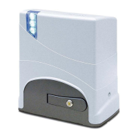
Verify green LEDs; check limit switch LEDs X and Y.

Junior 624 Installation Components

Core Operator and Mounting Hardware

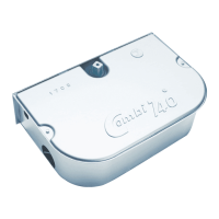
Lists operator, keys, base plate, anchor bolts, nuts, and washers.

Gear Rack and Associated Fasteners

Details nylon/30x8 gear racks and screws/bolts (not included).

Junior 624 Unit Components Diagram

Operator Status Indicators and Casing

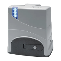
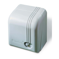
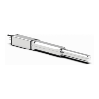
Describes LED lights, casing, and fixing screws for status indication.

Programmer, Control, and Unlock Mechanisms

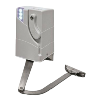
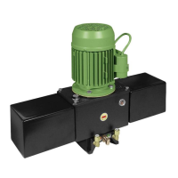
Lists programmer, support, fuse, gearbox, and manual unlock handle.

Motor, Limit Switch, and Power Components

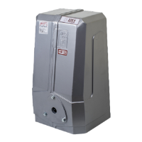
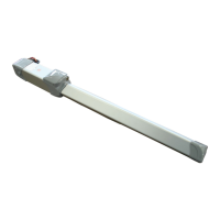
Details motor, microswitch, magnetic limit switch, pinion, and transformer.

Key Installation Components for Fig. 3

Photocells and Gate End Stop

Identifies Fit 55 photocells and the gate end stop component.

Operator, Receiver, and Safety Devices

Lists Junior 624, programmer, radio receiver, circuit breaker, and key-switch.

Limit Switch Types and Installation Setup

Magnetic Limit Switch Functionality

Explains the role and labeling of magnetic limit switches.

Left vs. Right Operator Installation Labels

Illustrates labels indicating SX (Left) and DX (Right) mounting positions.

Mechanical Limit Switch Functionality

Explains the role and labeling of mechanical limit switches.

Elpro 62 Programmer: DIP-Switches and Diagnostic LEDs

DIP-Switch Function Mapping

Details the operational functions assigned to each DIP-switch (1-12).

Interpreting Diagnostic LED Status

Explains the meaning of various LEDs (L2, L4, L5, etc.) for system status and faults.

Accessory Terminal Connections Overview

Lists common terminal connections for accessories like photocells and radio.

Elpro 62 Programmer: System Operation and Safety

Critical Safety and Installation Guidelines

Stresses professional installation, reading instructions, and power disconnection for PCB work.

Elpro 62: Microprocessor Control System

Describes the Elpro 62 as a microprocessor PCB for gate management and self-learning.

Detailed Diagnostic LED Status Guide

Comprehensive guide to LED meanings for system status and fault identification.

DIP-Switch Configuration for Operator Functions

Explains how DIP-switch settings (1-12) control various gate operator functions.

Electrical Connections for Gate Operator Accessories

Photocell, Safety Edge, and Key Selector Wiring

Details connections to terminals 1-7 for safety devices and controls.

Radio Contact and Warning Lamp Connections

Explains wiring for radio receivers and status warning lamps.

24 V Output for Flashers and DSA Control

Describes connections for 24Vdc flashers and DSA photocell transmitter power.

Connecting and Configuring Multiple Gate Operators

Master-Slave Configuration for Dual Operators

Guides setting up Master and Slave Elpro 62 units for controlling two operators.

Inter-Programmer Communication Cable

Specifies the 4-wire cable connection between the two Elpro 62 programmers.

Courtesly Lamp and Pedestrian Input Wiring

Details connections for courtesy lamps and pedestrian opening inputs.

Photocell and Second Operator NC Input Wiring

Explains connections for photocells and NC input from a second Junior operator.

Junior 624 Sliding Operator Core Functions

Force Adjustment and Safety Compliance

How to adjust force via trimmer and meet EN 12445/12453 safety standards.

Automatic vs. Semiautomatic Operation Modes

Differentiates automatic (open-pause-close) and semiautomatic (commanded open/close) modes.

Slowdowns and Obstacle Detection Features

Describes slowdown programming and the function for reversing on obstacle contact.

Photocell Re-closing and Safety Check Functions

Explains automatic re-closing after photocell passage and safety check functions.

Junior 624 Programming and Self-Learning Procedure

Initial Force Adjustment for Gate Operation

Adjust the Trimmer Force to move the gate smoothly and safely.

Gate Unlock and Initial Positioning Step

Unlock the gate manually, position it, and disconnect electrical power.

Initiating the Programming Sequence

Press and hold P button, re-apply power; LP LED will flash to indicate programming mode.

Learning Gate Travel and Slowdown Points

Use P button or transmitter to teach the operator the open/close travel and slowdown points.

Manual Operation, Battery Backup, and Troubleshooting

Manual Gate Operation via Unlocking Lever

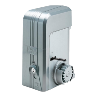
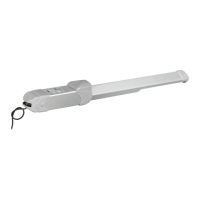
Use the coded key lever to unlock and manually move the gate; disconnect power.

Installing and Using Backup Batteries

Connect 12V backup batteries for operation during mains power failure.

Troubleshooting: No Gate Movement or LED Off

Diagnose issues like open NC contacts, blown fuses, or unlocked handle.

Troubleshooting: Amber LED Indicates Faults

Resolve amber LED faults related to obstacles, low force, or photocell issues.

Junior 624 Technical Specifications and Compliance

Key Electrical and Mechanical Data

Lists power, voltage, current, weight, speed, protection, and operating temperature.

Manufacturers Declaration of Conformity

Statement of compliance with EU directives and safety standards by Meccanica Fadini.

fadini Junior 624 Specifications

General IconGeneral
Brandfadini
ModelJunior 624
CategoryGate Opener
LanguageEnglish

Related product manuals