Do you have a question about the Fagor 5CFB-90X and is the answer not in the manual?
The hood is designed for exhausting or filter versions.
Describes using the hood for exhausting fumes to the outside.
Details minimum distance requirements for installation above the hob.
Explains how to connect the hood to the electrical supply.
Covers wall mounting, suitability of materials, and fixing the hood.
Provides instructions on how to use the cooker hood.
Explains how to operate the hood using a keyboard control panel.
Explains the indicators for grease and carbon filter saturation.
Instructions on how to reset filter saturation indicators.
General maintenance instructions for the cooker hood.
Guidance on how to clean the cooker hood internally and externally.
Details on replacing and maintaining the charcoal filter for filter versions.
Step-by-step guide for replacing the hood's light bulbs.
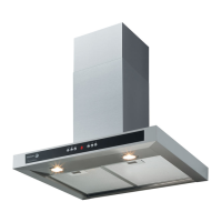
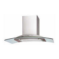
This document outlines the installation, operation, and maintenance of the Fagor 5CFB-90X and 5CFB-60X Wall Canopy cooker hoods. It serves as a comprehensive guide for users to ensure proper and safe functioning of the appliance.
The Fagor wall canopy cooker hood is designed to efficiently remove cooking fumes and odors from your kitchen, offering both ducted (exhausting) and recirculating (filter) versions. In the ducted version, the hood expels fumes to the outside through a top air outlet, requiring an exhaust pipe and clamps (not supplied). For the filter version, where external venting isn't possible, the hood utilizes an activated carbon filter and a deflector to recycle purified air back into the kitchen through a top grille. Models without a suction motor are exclusively for ducted operation and must be connected to an external suction device.
The installation process begins with preliminary steps, including disconnecting the hood from the electrical supply and removing the fat/s and carbon filters. It's crucial not to tile, grout, or silicone the appliance to the wall, as it's designed for surface mounting only. The wall/ceiling must be robust enough to support the hood's weight. The manual provides detailed instructions for assembling the chimney flue support/bracket and, if applicable, the deflector. These components are designed to be adjustable to match the internal width of the telescopic chimney flue. Specific models, such as those illustrated in Fig. 1D/8D, 1E/8E, and 1Q/8Q, require the removal and preservation of screws that temporarily fix the flue units for transport reasons. Users are advised to disassemble these parts to facilitate installation and note how they are fixed to ensure correct reassembly. Before mounting, it's important to verify that the metal band holding the lamp and filters is securely attached to the front, adjusting its position if necessary.
The installation sequence involves resting the suction unit on a flat surface and threading the lower part of the hood onto it, followed by making all electrical connections between the two parts. The cooker hood is then permanently fixed to the suction group with screws. A center line is drawn on the wall, extending up to the ceiling, to aid in positioning. The drilling template is used to mark perforation points, ensuring the hood's bottom edge aligns with the template and maintaining the minimum required distance from the cooker top (50 cm for electric cookers, 65 cm for gas or mixed cookers). The lower support bracket is fixed to the wall using screws and wall-dowels. For specific models (Fig. 1Q/10Q), a central bracket is also fixed above the lower bracket. If supplied dismantled, hooks are fixed to the aspiration group, and the hood is hung onto the lower bracket. Adjustments for distance from the wall and horizontal position are then made. Permanent drill holes are marked, drilled, and wall screw anchors are inserted. The flue support bracket is applied to the wall, marked, drilled, and fixed with screws. The hood is then hooked onto the bottom bracket and fixed into its final position. Finally, the discharge pipe is connected to the suction motor unit, and electrical connections are completed. For filter versions, the deflector is fixed to the chimney support bracket, and the pipe is connected to the deflector's connection ring. The chimney stacks are applied and fastened to the support. For models with optical fiber lighting or control panels on the chimney flue, specific instructions are provided for accessing and connecting these components. The bottom section of the chimney is slid down to cover the suction unit, and the lower section is fixed with screws. The carbon filter frame and fat/s filters are then remounted, and the hood's functioning is checked.
The Fagor cooker hood offers various control interfaces, including keyboard and 5-key or 6-key electronic models, as well as display models.
For optimal performance, it is recommended to switch on the cooker hood 5 minutes prior to cooking and leave it on for about 15 minutes after cooking. The high suction speed should be used for concentrated kitchen vapours. If the hood malfunctions, briefly disconnecting it from the mains power supply for about 5 seconds and then reconnecting it can often resolve the issue. Always press the fan off button before disconnecting the hood from the mains supply.
Regular maintenance is crucial for the hood's efficiency and longevity.
The manual emphasizes several safety precautions:
By following these guidelines, users can ensure the safe, efficient, and long-lasting operation of their Fagor wall canopy cooker hood.
| Type | Wall-mounted |
|---|---|
| Housing Material | Stainless Steel |
| Number of speeds | 3 |
| Lighting Type | Halogen |
| Number of bulbs | 2 |
| Bulb power | 20W |
| Grease filter type | Aluminum |
| Width | 90 cm |
| Airflow | 650 m³/h |
| Number of Motors | 1 |
| Control Type | Push Button |
| Material | Stainless Steel |