Part number
055-IPI-089M
055-IPI-089-F
032-IPI-009-3M
032-IPI-099-3F
Description
Male connector (Feedback)
Female connector (Input)
Male cable w/one connector
Female cable w/one connector
Apply a minimum amount of pipe compound to the male
threads of the air line only. Do Not use teflon tape as a
sealant. Start with the third thread back and work away
from the end of the pipeline to avoid the possibility of getting
pipe compound into the air lines.
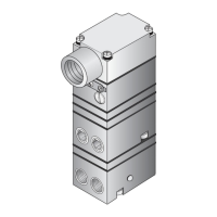
The inlet and outlet ports are labeled on the side of the
transducer. Tighten connections securely. Avoid under-
sized fittings that will limit the flow through the transducer.
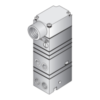
For more information, see Figure 1. “T7900 Outline Dimen-
sions” on page 1.
NOTES:
Electric Connection
Pneumatic Connections
Clean all pipelines to remove dirt and scale before
installation.
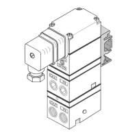
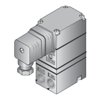
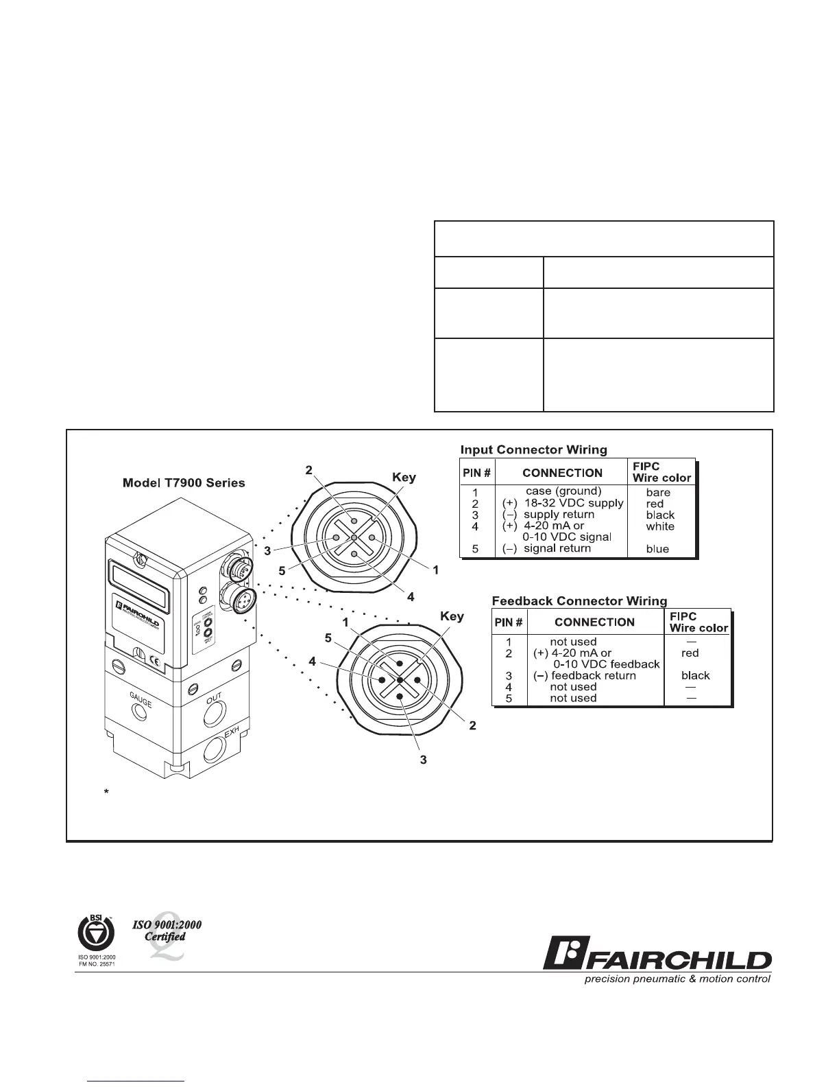
Figure 2. Electrical Connections.
For the T7900 Transducer, make connections as shown
below in Figure 2. “Electrical Connections”. For compatible
cord sets and connectors refer to Table 1. below.
For signal lines of six feet or less, 22 gage wire may be used.
For longer signal lines, use 18 gage wire. Shielded cable
Must Be Used for the signal lines for noise immunity.
Oil free air is required. Use a filter to remove
dirt and liquid in the air line ahead of the
transducer. If an air line lubricator is used, it
MUST be located downstream to avoid inter-
ference with transducer performance.
Supply pressure must be no less than 5 psig,
[0.35 BAR], (35 kPa), above maximum output.
II-500T7900
Litho in USA
Rev. C 9/02
(3 meter)
(3 meter)
Table 1. T7900 Cables and Connectors (Sold Separately)
1
Colors apply only to FIPC DeviceNet compatible cables.
1
1
 Loading...