EasyManua.ls Logo

Fairchild T6000 User Manual

Fairchild T6000
35 pages
To Next Page IconTo Next Page
Page #1 background imageLoading...
Page #1 background image
FAIRCHILD T6000 Electro-Pneumatic Transducers
Standard and Extended Ranges
Installation, Operation & Maintenance Instructions
Note: Unused IN and OUT
Ports are plugged (typical
)
Figure 1. TA6000 Outline
Dimensions
Figure 2. TT6000 Outline
Dimensions
Figure 3. TD6000 Outline
Dimensions
GENERAL INFORMATION
The Model T6000 can be mounted directly onto a at surface using two 10-32 screws.
The Model T6000 is supplied with a Mounting Kit 16799-1 for Panel or Wall Mounting. For detailed mounting
information, see page 3, Figures 6, 7 & 8.
1/2-14
NPT
5 11/64
131.5
4 39/64
117.2
1/2
12.7
1
25.4
25/32
19.7
25/64
9.8
Use two
10-32
Screws for
Mounting
3 7/16
87.2
3 3/64
77.5
2 1/4
57.2
1 33/64
38.7
Orifice
Do Not
Remove
Plugs
(typ.)
Do Not
Remove
Plugs
(typ.)
1/4 NPT
Outlet Port (2)
(typical)
1/4 NPT
Inlet Port (2)
(typical)
Vent
ZERO
SPAN
OUT
OUT
OUT
OUT
IN
IN
IN
IN
3 43/64
93.3
3 7/64
79.0
1 59/64
49.0
Extended Range
OUT
OUT
IN
IN
3 3/32
78.7
1 33/64
38.7
5 11/64
131.5
1/4 NPT
Inlet
Port (2)
(typical)
Do Not
Remove
Plugs
(typical)
1/4 NPT
Outlet
Port (2)
(typical)
4 53/64
122.8
ZERO
SPAN
+
_
_
3 21/64
84.6
3 43/64
93.3
OUT
OUT
IN
IN
ZERO
SPAN
1 31/64
37.8
1 1/8
28.6
2 7/16
61.8
4 19/32
116.5
1 11/32
34.1
1/4 NPT
Inlet
Port (2)
(typical)
Do Not
Remove
Plugs
(typical)
1/4 NPT
Outlet
Port (2)
(typical)
90 Alternating
Positions
3 5/64
78.3
1

Other manuals for Fairchild T6000

Question and Answer IconNeed help?

Do you have a question about the Fairchild T6000 and is the answer not in the manual?

Fairchild T6000 Specifications

General IconGeneral
Accuracy±0.5% of Span
Linearity±0.5% of Span
Hysteresis±0.25% of Span
Operating Temperature-40° to 150°F / -40° to 65°C
TypePneumatic
Power SupplyPneumatic
Input Signal3-15 psig, 0.2 - 1.0 Bar, 20-100 kPa
Output3-15 psig, 0.2 - 1.0 Bar, 20-100 kPa

Summary

Installation and Mounting

Mounting Kit 16799-1

Details the included mounting kit for general use.

DIN Rail Mounting Kit 16893

Describes the DIN rail mounting kit for the T6000.

Mounting Kit 19254-1

Explains the mounting kit for 2-inch pipe installations.

Connections and Maintenance

Pneumatic Connection

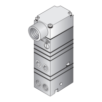
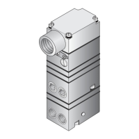
Details on connecting the transducer to pneumatic lines.

Electric Connection

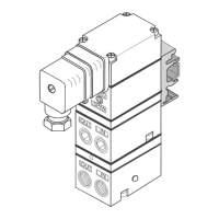
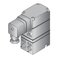
Instructions for electrical connections, including DIN connector changes.

Troubleshooting

Common problems, solutions, and warnings for troubleshooting.

Calibration and Adjustments

Equipment Required for Calibration

Lists necessary pneumatic and electric tools for calibration.

Forward Acting Mode Adjustment

Step-by-step guide for adjusting the transducer in forward acting mode.

Reverse Acting Mode Adjustment

Step-by-step guide for adjusting the transducer in reverse acting mode.

Split Range Operation

Explains the capability for split range configurations.

Hazardous Location Installation

ATEX and IECEX Intrinsically Safe

Conditions for ATEX and IECEX intrinsically safe certifications.

FM and CSA Intrinsically Safe/Nonincendive

Conditions for FM and CSA intrinsically safe/nonincendive certifications.

Wiring in Hazardous Areas

Guidelines for wiring practices in hazardous environments.

Limitations and Exceptions

Specifies limitations and exceptions for installation types.

Conditions Of Certification

Related product manuals